相關活動
- 呼朋引伴,好康抽獎:學習STM32,千元開發板等你拿! ,即日起至 9/30 日止,簡單完成三步驟,同樣有機會獲得好禮STMicroelectronics 開發板(STM32F746),讓您看完文章與影片教學後更能實際操作,深入了解AI在MCU的應用!
- 熱血競賽,缺你不可:iThome鐵人賽 ,即日起至 9/16 日止,只要連續 30 天分享你在 Arm 技術、平台上的實戰經驗,除了既定獎項,還有機會抽中 Surface Pro X、Amazon Kindle Paperwhite 電子書閱讀器、STMicroelectronics 開發板(STM32F746)等多項好禮。
作者:謝昇宏
筆者最近取得一個有趣的套件,是國內開發者不陌生的STM32系列之一的IoT開發套件 - STM32F746G-DISCOVERY(DISCO-F746NG)探索套件。它的功能相當完整,其運算核心是基於 Arm® Cortex®-M7 的 STM32F746NG微控制器,具備強大的運算能力。它同時整合了4.3吋的彩色電容式觸控螢幕、USB OTG、Audio Codec、Micro SD 插槽、雙數位麥克風,也內建乙太網路10/100Mb來延伸網路應用,從而簡化應用程序的開發,能快速驗證產品與想法。
繼承STM32的優良傳統,此套件也支持易於開發的Arduino IDE環境,讓原本使用Arduino的Maker可以快速上手,更可以直接使用相容於Arduino開源函式庫,共享相關社群的開發資源。不僅如此,這個套件提供相容於ARDUINO Uno V3的擴充插槽,讓擴展能力大幅提升。

(圖片來源:www.st.com)
本開發板引出的GPIO如下圖:
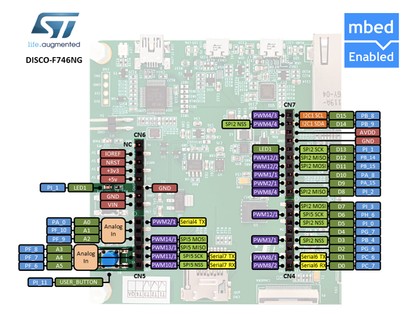
(圖片來源:os.mbed.com)
Arduino 開發環境安裝
看到這樣強大的功能與完善的支援介面,你是不是和筆者一樣躍躍欲試了呢?別急,先把Arduino開發環境安裝起來吧。
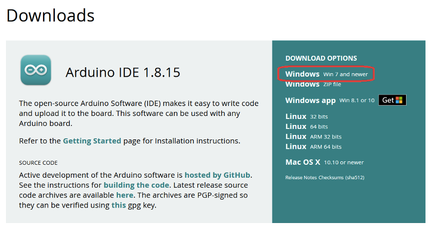
(1) 請先下載Arduino IDE開發環境
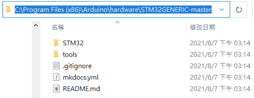
(2) 為Arduino IDE安裝STM32的支援,從Github下載最新的版本,解壓縮至 C:\Program Files (x86)\Arduino\hardware
(註:這個路徑依照你的Arduino安裝路徑可能略有不同)
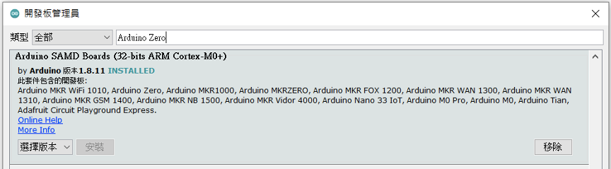
(3) 安裝編譯器arm-none-eabi-gcc,從開發板管理員搜尋並安裝 Arduino SAMD Boards (32-bits Arm Cortex-M0+) 版本1.8.11
(4) 編譯STM32GENERIC時會有錯誤,請使用patch檔覆寫arm-none-eabi-gcc裡的原始碼,共有4個檔會被覆寫。
Patch檔下載路徑: https://github.com/fw-box/arm-none-eabi
解壓縮並覆寫到C:\Users\myname\AppData\Local\Arduino15\packages\arduino\tools\arm-none-eabi-gcc\7-2017q4\arm-none-eabi (註:myname要改成你的使用者名稱)
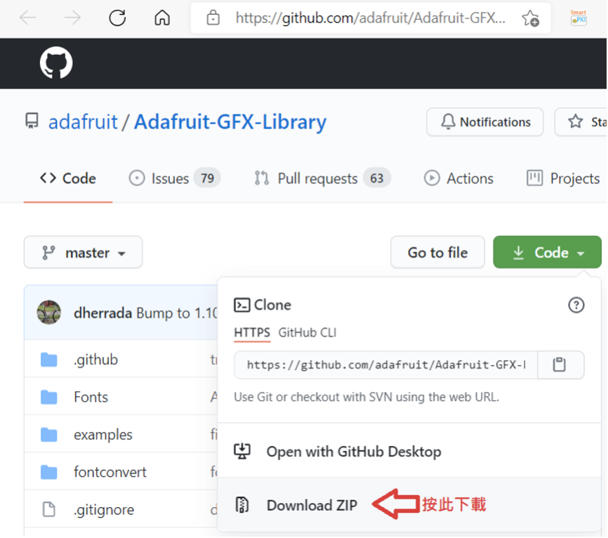
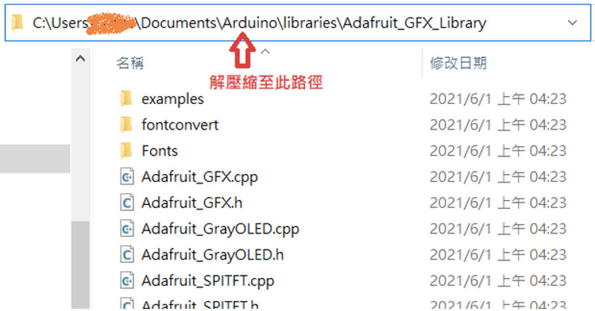
(5) 下載下列4個必需的函式庫並解壓縮至C:\Users\myname\Documents\Arduino\libraries (註:myname要改成你的使用者名稱)
https://github.com/adafruit/Adafruit-GFX-Library
https://github.com/fw-box/Adafruit_BusIO
https://github.com/stm32duino/LwIP
https://github.com/fw-box/STM32Ethernet
下載方法如下圖,下載下來會是一個壓縮檔。解壓縮一個新的函式庫至libraries後,需要重新啟動Arduino IDE來掃描載入新的函式庫。
下載並安裝開發板的驅動程式
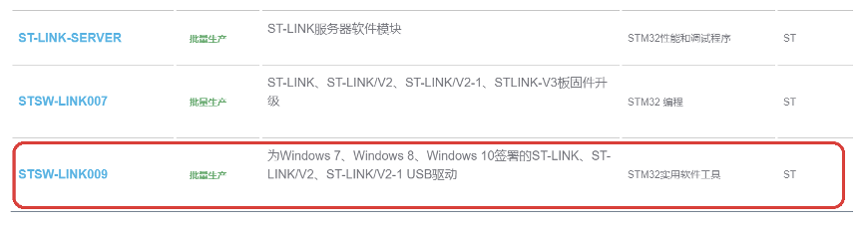
請到ST官網介紹此套件的「工具與軟體」區,找到ST-LINK驅動程式,按下下圖紅框內的連結後會跳出註冊畫面,註冊後www.st.com會發送下載的網址到註冊信箱。下載後解壓縮,並以系統管理員身份執行stlink_winusb_install.bat安裝驅動程式。
編譯燒錄設定
選擇開發板Discovery F746NG;Upload method改成Mass Storage:
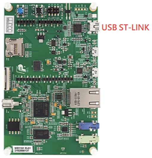
紅字為USB ST-LINK連結埠
開始上傳(燒錄)前,請用mini USB線連接PC與開發板的USB ST-LINK。然後把序列埠改成新出現的COM port,上圖的範例是COM20。
程式範例
安裝好了,我們來執行幾個程式範例吧。
1. 數位GPIO read, write
這功能與一般Arduino模式一樣,按鈕USER_BTN是背面的藍色按鈕,可供使用者自訂功能。
LED_BUILTIN在黑色按鈕旁邊,範例程式運作後會開始閃爍,按下藍色按鈕後閃爍速度會變快。
1.    void setup()

2.  {

3.    pinMode(USER_BTN, INPUT);

4.    pinMode(LED_BUILTIN, OUTPUT);

5.  }

6.

7.  void loop()

8.  {

9.    digitalWrite( LED_BUILTIN  , HIGH ); // led on

10.

11.   if ( digitalRead( USER_BTN ) )

12.     delay(10); // blink faster if button is pressed

13.   else

14.     delay(100);

15.

16.   digitalWrite( LED_BUILTIN, LOW ); // led off

17.   delay(100);

18. }
程式碼來源 : UserButton.ino
2. ADC讀取
此套件ADC的解析度最高為12 bits,數值範圍是0 ~ 4096。為保持與Arduino UNO的相容性,A0 ~ A5皆有被定義,可以直接使用。程式碼中P開頭的GPIO名是為本開發板所定義,A0可以用PA0取代、A1可以用PF10取代,其它GPIO對應如程式碼所示。此範例會不斷地把A0讀到的數值寫到序列埠,請開啟序列埠監控視窗查看結果。
// the setup routine runs once when you press reset:

2.  void setup() {

3.    // initialize serial communication at 115200 bits per second:

4.    Serial.begin(115200);

5.    delay(1000);

6.

7.    // configure the ADC for 12 Bits

8.    analogReadResolution(12);

9.

10.   Serial.println();

11.   Serial.printf("PA0:%d, A0:%d\n", PA0, A0);

12.   Serial.printf("PF10:%d, A1:%d\n", PF10, A1);

13.   Serial.printf("PF9:%d, A2:%d\n", PF9, A2);

14.   Serial.printf("PF8:%d, A3:%d\n", PF8, A3);

15.   Serial.printf("PF7:%d, A4:%d\n", PF7, A4);

16.   Serial.printf("PF6:%d, A5:%d\n", PF6, A5);

17. }

18.

19. // the loop routine runs over and over again forever:

20. void loop() {

21.   // read the input on analog pin 0:

22.   int sensorValue = analogRead(PA0);

23.   // print out the value you read:

24.   Serial.printf("PA0=%d\n", sensorValue);

25.   delay(1000); // delay in between reads for stability

26. }
程式碼來源 : AnalogtReadSerial_12bit.ino
3. 使用SDRAM
DISCO-F746NG擁有8MB(64 Mbits)可用的SDRAM,但系統會用掉一些,所以無法完整配置8MB記憶體。下列程式碼是配置7MB的記憶體的範例。
1.   void setup()

2.  {

3.      Serial.begin(115200);

4.  }

5.  void loop()

6.  {

7.      uint32_t size = 7 * 1024 * 1024; // 7MB

8.      Serial.printf("Allocating %d buffer\n", size);

9.

10.     uint8_t *data = (uint8_t*)malloc(size);

11.     if (data == NULL)

12.         Serial.println("Malloc failed!");

13.     else

14.         Serial.println("Success");

15.

16.     free(data);

17.     delay(5000);

18. }
I2C存取
請把I2C模組的SCL、SDA接至下面的腳位 – I2C1_SCL、I2C1_SDA,記得模組的3V3、GND也要接上。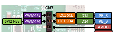
以下程式會掃描出模組的I2C位址。請注意在呼叫Wire.begin();之前要先呼叫Wire.stm32SetInstance(I2C1); Wire.stm32SetSDA(PB9); Wire.stm32SetSCL(PB8); 來設定I2C連接的腳位,因為DISCO-F746NG擁有4組I2C(I2C1 ~ I2C4),對應到Arduino UNO擴充插槽I2C腳位的是I2C1。
#include

2.

3.  void setup()

4.  {

5.    Wire.stm32SetInstance(I2C1);

6.    Wire.stm32SetSDA(PB9);

7.    Wire.stm32SetSCL(PB8);

8.    Wire.begin();

9.

10.   Serial.begin(115200);

11.   delay(5000);

12.   Serial.println("\nI2C Scanner");

13. }

14.

15. void loop()

16. {

17.   byte error, address;

18.   int nDevices;

19.

20.   Serial.println("Scanning...");

21.   delay(2000);

22.

23.   nDevices = 0;

24.   for (address = 1; address < 127; address++ ) {

25.     // The i2c_scanner uses the return value of

26.     // the Write.endTransmisstion to see if

27.     // a device did acknowledge to the address.

28.     Wire.beginTransmission(address);

29.     Wire.write(0);

30.     error = Wire.endTransmission();

31.

32.     if (error == 0) {

33.       Serial.print("I2C device found at address 0x");

34.       if (address < 16)  Serial.print("0");

35.       Serial.print(address, HEX);

36.       Serial.println("  !");

37.       nDevices++;

38.     }

39.     else if (error == 4) {

40.       Serial.print("no device found at address 0x");

41.       if (address < 16) Serial.print("0");

42.       Serial.println(address, HEX);

43.     }

44.   }

45.   if (nDevices == 0) {

46.     Serial.println("No I2C devices found\n");

47.     Serial.println("Did you configure the chip select for your device?\n");

48.   }

49.   else

50.     Serial.println("done\n");

51.

52.   delay(5000);           // wait 5 seconds for next scan

53. }
程式碼修改自 : I2cScanner.ino
繪圖與觸控螢幕
觸控IC接在I2C3的位置,所以要先做I2C的初始化。因為篇幅的關係,僅列出主程式,請從Github這個連結取得stm32_ub_touch_480x272.h與stm32_ub_touch_480x272.cpp,與主程式放在同一個目錄。
1.    #include

2.  #include "stm32_ub_touch_480x272.h" // 觸控螢幕

3.  #include "LTDC_F746_Discovery.h" // 繪圖

4.

5.  LTDC_F746_Discovery tft;

6.

7.  uint8_t UB_I2C3_ReadByte(uint8_t addressI2cDevice, uint8_t registerId)

8.  {

9.    uint8_t result;

10.   addressI2cDevice = addressI2cDevice >> 1;

11.

12.   Wire.beginTransmission( addressI2cDevice  );

13.   Wire.write( registerId );

14.   uint8_t error;

15.   error = Wire.endTransmission();

16.

17.   Wire.requestFrom( addressI2cDevice, (uint8_t) 1 , (uint8_t) true );

18.

19.   while ( Wire.available() < 1 );

20.

21.   result = Wire.read() ;

22.

23.   if (error)Serial.println("I2C error");

24.

25.   return result;

26. }

27.

28. void setup()

29. {

30.   Serial.begin(115200);

31.   delay(1000);

32.

33.   Wire.stm32SetInstance(I2C3);

34.   Wire.stm32SetSDA(PH8);

35.   Wire.stm32SetSCL(PH7);

36.

37.   Wire.begin();

38.

39.   UB_Touch_Init();

40.

41.   // The buffer is memory mapped

42.   // You can directly draw on the display by writing to the buffer

43.   uint16_t *buffer = (uint16_t *)malloc(2*LTDC_F746_ROKOTECH.width * LTDC_F746_ROKOTECH.height);

44.

45.   tft.begin((uint16_t *)buffer);

46.   tft.fillScreen(LTDC_WHITE);

47. }

48.

49. void loop()

50. {

51.   UB_Touch_Read();

52.

53.   int x = Touch_Data.xp;

54.   int y = Touch_Data.yp;

55.

56.   Serial.printf("(%d, %d)\n", x, y);

57.   tft.fillCircle(x, y, 3, LTDC_BLUE);

58.

59.   delay(10);

60. }
程式碼修改自 : TouchDisplay.ino
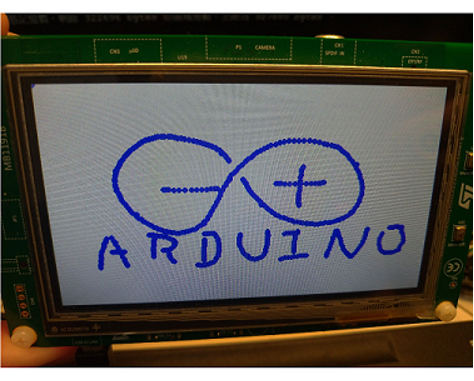
程式執行畫面,用手指在觸控螢幕上畫圖,類似小畫家的效果。
透過Ethernet連接至網際網路
以下是一個使用HTTP GET連線至http://example.com的範例,執行後會把Server的回應顯示在序列埠監控視窗。
1.    #include

2.  #include

3.

4.  EthernetClient client;

5.

6.  // random MAC address

7.  byte mac[] = { 0xDE, 0xAD, 0xBE, 0xEF, 0xFE, 0xED };

8.

9.  void setup() {

10.     Serial.begin(115200);

11.

12.     Serial.println("Connecting to Ethernet");

13.

14.     if (!Ethernet.begin(mac)) {

15.         Serial.println("ERROR: Could not connect to ethernet!");

16.         while(1);

17.     }

18.

19.     Serial.println("Connecting to example.com");

20.

21.     if (!client.connect("example.com", 80)) {

22.         Serial.println("ERROR: Could not connect to example.com!");

23.         while(1);

24.     }

25.

26.     Serial.println("Connected, sending request");

27.

28.     client.println("GET / HTTP/1.1");

29.     client.println("Host: example.com");

30.     client.println();

31.     client.flush();

32.

33.     Serial.println("Request sent, printing response");

34. }

35.

36. void loop() {

37.     if (client.available()) {

38.         char c = client.read();

39.         Serial.print(c);

40.     }

41.

42.     if (!client.connected()) {

43.         Serial.println();

44.         Serial.println("disconnecting.");

45.         client.stop();

46.         while (1);

47.     }

48. }
更多範例
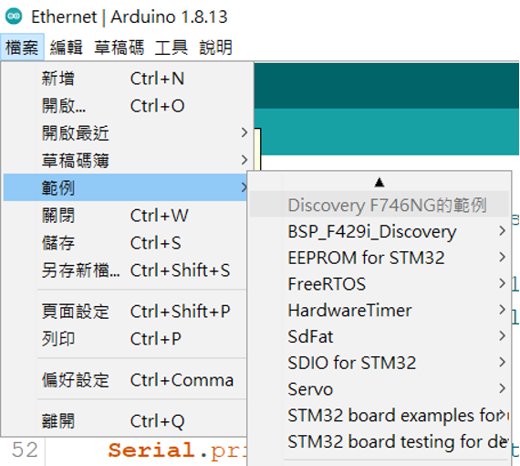
可以從以下位置找到更多範例:
Arduino ID選單的檔案=>範例=>Discovery F746NG的範例
結語
DISCO-F746NG使用Arm架構的M7微控制器,效能強大,運作起來相當流暢,而且本身已經具備彩色觸控螢幕、Audio、麥克風與Ethernet,不用再另外接模組。筆者測試過其觸控定位功能,相當精準且反應快速,很適合擔任顯示與人機互動的主機。再加上它支援易入門的Arduino IDE,開發者可在網路上找到很多參考資料,不怕碰到問題時搜尋不到解決方法。
看完本文的介紹,你是不是發現這個套件相當適合來實現你心中「某個」創意的原型設計呢?上手一塊來玩玩看吧~
延伸閱讀
開發板規格:
- STM32F746NGH6 Arm® Cortex® core-based 微處理器包含1 Mbyte Flash memory 與 340 Kbytes RAM, 216MHz max frequency, BGA216 封裝
- 4.3吋的彩色電容式觸控螢幕, 解析度 480×272
- Ethernet compliant with IEEE-802.3-2002
- USB OTG HS
- USB OTG FS
- SAI 音效解碼器
- 雙ST-MEMS 數位麥克風
- 128-Mbit Quad-SPI Flash memory
- 128-Mbit SDRAM (可存取64 Mbits)
- 1個使用者定義按鈕與1個 reset 按鈕
板上連接器:
- Camera
- microSD™ 卡
- RF-EEPROM daughterboard connector
- 2×USB with Micro-AB
- 乙太網路10/100Mb RJ45
- SPDIF RCA input connector
- 音效輸入與輸出接口
- 立體聲輸出
- ARDUINO Uno V3 擴充插槽
- 彈性的電源供應選擇 : ST-LINK, USB VBUS or external sources
- 板上提供電源 : 3.3 V or 5 V
- STM32Cube MCU Package : 包含豐富的函式庫與範例
- ST-LINK/V2-1 除錯/燒錄介面, 虛擬串口
- 支援各種主流強大的整合式開發環境 IAR™, Keil®, GCC-based IDEs, and Arm® Mbed™
輸入輸出:
- GPIOs (168) with external interrupt capability
- 12-bit ADCs with 24 channels (3)
- 12-bit DAC channels (2)
- USART/UART (8)
- I2C (4)
- SPI (6)

- 【STM32開箱文】教你上手DISCO-F746NG探索套件,Arduino也相容! - 2021/08/25
訂閱MakerPRO知識充電報
與40000位開發者一同掌握科技創新的技術資訊!


