作者/圖片來源:CAVEDU 教育團隊
Google Teachable Machine最近推出了新的神經網路匯出方案,需要使用Arduino Nano 33 BLE Sense 搭配 OV7670相機模組,就可以讓Arduino透過匯出的TensorFlow Lite檔案來做到邊緣裝置端的「即時」影像分類。
說是即時,但都在Arduino上執行了,當然不可能快到哪裡去,圖片也是黑白的,這都是針對Arduino的運算能力來考量,且Arduino Nano 33 BLE Sense與OV7670相機模組這兩個買起來也快接近Raspberry Pi 3了。
另外,ESP32-CAM搭配TensorFlow Lite很早就能做到深度學習視覺分類應用,但用Teachable Machine可以自行訓練所要目標,也是不錯的選擇。老話一句,看您的專案需求來決定使用哪些軟硬體喔!
本文會帶您完成相關的軟硬體環境設定,並操作Teachable Machine透過相機模組來搜集照片、訓練神經網路,最後匯出檔案給 Arduino執行即時影像(灰階)分類!別說這麼多了,先看影片!
手邊有設備的朋友歡迎跟著這一篇文章做做看,也歡迎與我們分享成果喔。教學中會用到Processing來呈現辨識結果,也歡迎從阿吉老師的Processing小教室來學習Processing的應用喔~
以下操作步驟根據Teachable Machine 網站說明
硬體
Arduino Nano 33 BLE Sense / Nano 33 BLE
目前指定只能用這片板子,其他板子編譯會有問題,看看之後有沒有機會在別的板子上執行囉,詳細規格請參考原廠網站。
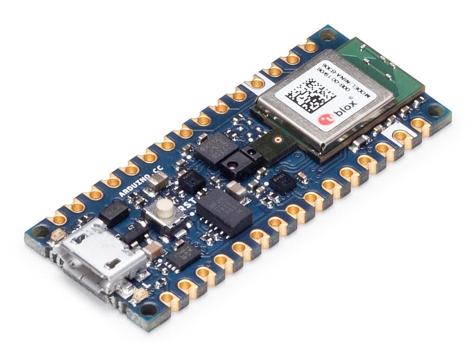
(圖片來源: Arduino 網站)
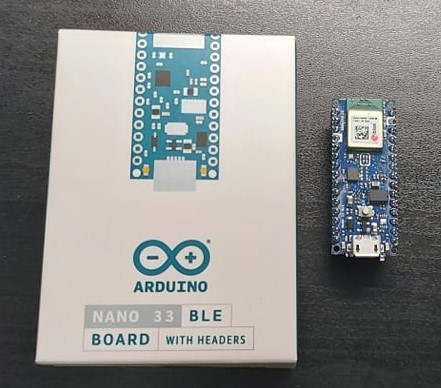
以下是實物照片,板子都愈來愈小呢(視力挑戰)
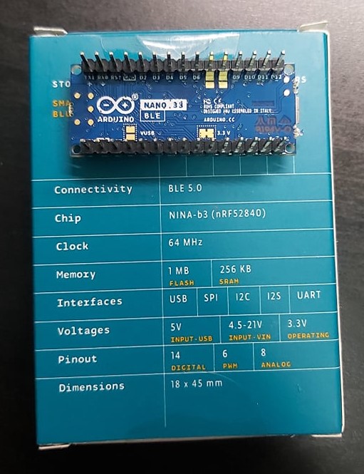
重要資訊有寫在盒裝背面,當然看原廠網站是最快的。
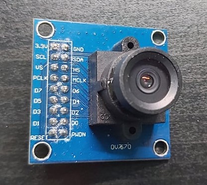
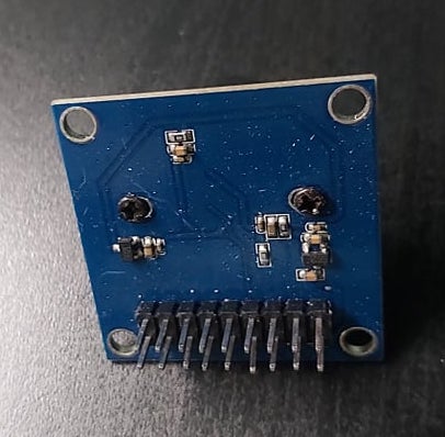
OV7670 相機模組
由OmniVision推出的相機模組,本範例會把它接在Arduino上,並直接從Teachable Machine來擷取黑白影像作為訓練資料集。
規格請點我,實體照片如下。
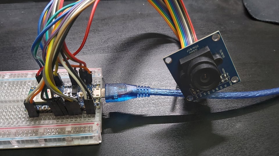
接下來是大工程,使用母母杜邦線並根據下表完成接線,請細心完成囉。
| OV7670 相機模組腳位名稱 | Arduino 腳位名稱 |
| 3.3v | 3.3v |
| GND | GND (所有GND都可使用) |
| SCL/SIOC | A5 |
| SDA/SIOD | A4 |
| VS/VSYNC | D8 |
| HS/HREF | A1 |
| PCLK | A0 |
| MCLK/XCLK | D9 |
| D7 | D4 |
| D6 | D6 |
| D5 | D5 |
| D4 | D3 |
| D3 | D2 |
| D2 | D0 / RX |
| D1 | D1 / TX |
| D0 | D10 |
完成如下圖。
軟體 – Arduino IDE
請先取得Arduino IDE,我使用Arduino 1.8.5。OV7670相機模組需要匯入一些函式庫,請根據以下步驟操作:
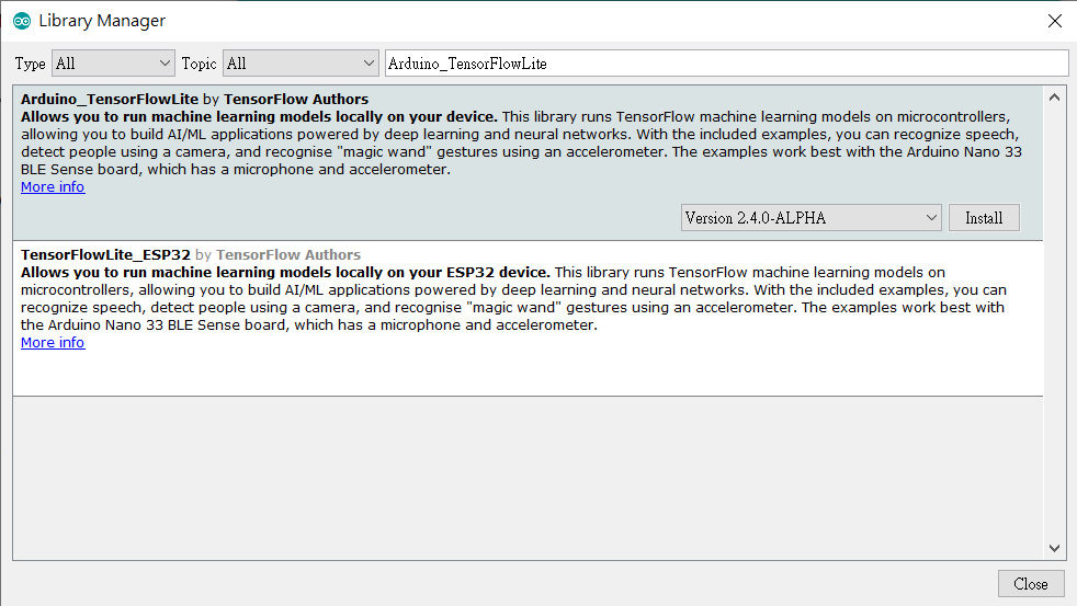
- 安裝Arduino_TensorFlowLite函式庫:Arduino IDE,請開啟 Tools -> Manage Libraries,並搜尋 Arduino_TensorFlowLite,請選擇Version 2.4.0-ALPHA之後的版本,點選安裝。
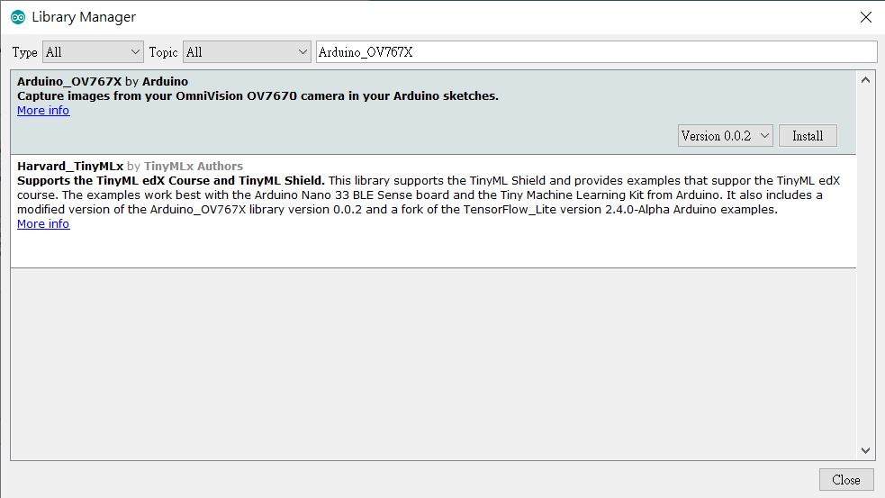
- 安裝Arduino_OV767X 函式庫:搜尋 Arduino_OV767X並安裝。
軟體 – Processing
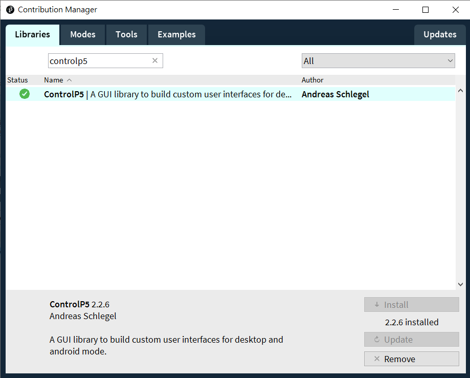
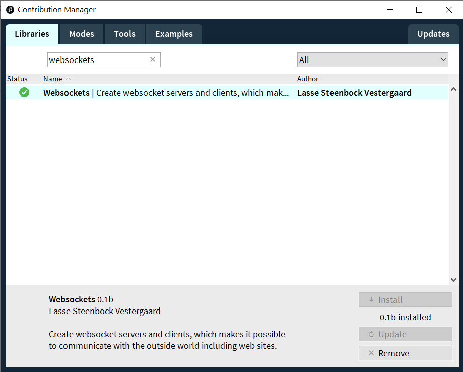
Processing是用來連接Arduino與Teachable Machine。請先下載 Processing IDE 3.X 版本。下載好Processing IDE之後,請開啟 Sketch -> Add Library -> Manage Libraries,並搜尋ControlP5與Websockets,點選安裝就完成了。
軟體 – Teachable Machine
根據網站說明,Embedded model是標準影像分類神經網路模型的迷你版,因此可在微控制器上運行。

這應該是最簡單的地方啦,但在操作TM之前要先完成上述的軟硬體設定。完成之後請根據以下步驟操作:
- 下載TMUploader Arduino Sketch,解壓縮之後於Arduino IDE開啟同名的.ino檔。板子類型要選擇Arduino Nano 33,COM port也要正確設定否則將無法燒錄。本程式負責把Arduino所拍攝的影像送往Processing。
- 下載TMConnector Processing Sketch,解壓縮之後於 Arduino IDE 開啟同名的 .pde 檔。點選左上角的執行(Play)鍵,會看到如下的畫面,並列出可用的 COM port 與連線狀態。
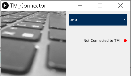
- 請由畫面中來選擇您的 Arduino,如果列出很多裝置不知道怎麼選的話,可由 Arduino IDE 中來交叉比對。順利的話就會在 Processing 執行畫面中看到相機的即時預覽畫面。
如果畫面停頓或是沒有畫面,請檢查接線是否都接對了。如果畫面有更新但是模糊,請轉動相機模組前端圓環來調整焦距。 - 回到Teachable Machine網站,新增一個Image Project專案。先點選Device,再點選 [Attempt to connect to device] 選項,順利的話應該就可以看到OV7670的畫面了。
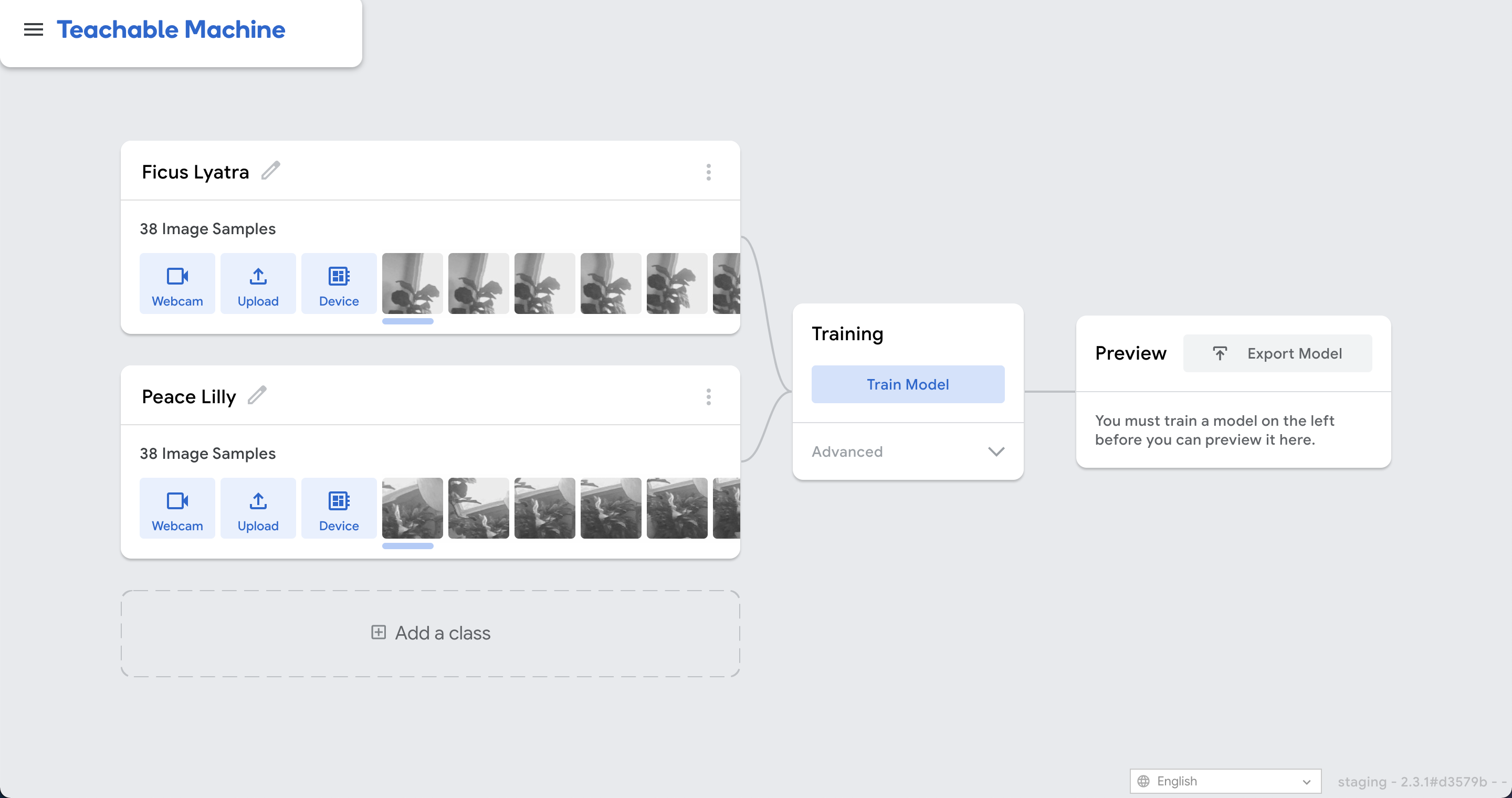
收集資料與訓練
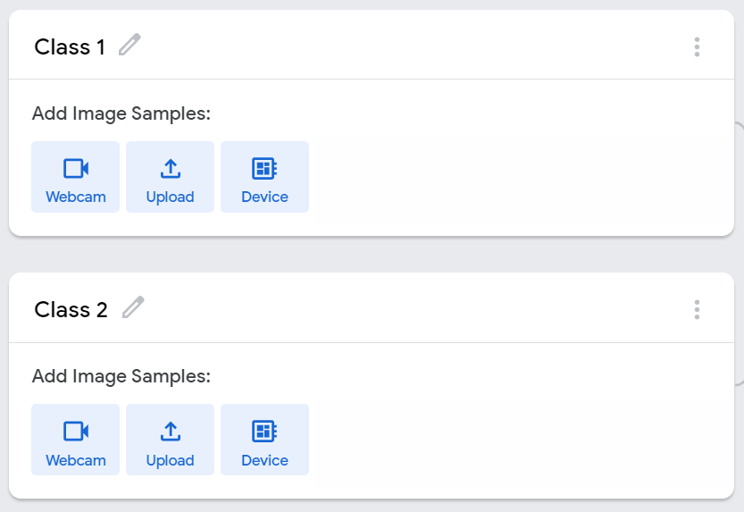
接下來的步驟就一樣了,請用您的照相機來蒐集想要訓練的圖片吧,圖片格式為 96 x 96 灰階。請用相機對準想要辨識的物體,從 [webcam] 選項來收集照片。請注意,即便用 [Upload] 選項去上傳彩色照片,訓練完的模型一樣只能接受單色(灰階)輸入。請盡量讓資料收集與後續測試時使用同一個相機模組(原場考照的概念~)
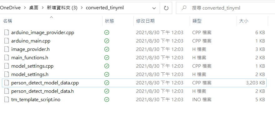
訓練完成(很快)之後,於 Teachable Machine 右上角點選 [Export Model],於彈出畫面中選擇 Tensorflow Lite 並勾選下方的 Tensorflow Lite for Microcontrollers ,最後點選 [Download my model] 就好了!轉檔需要稍等一下(有可能要幾分鐘),完成就會下載一個 converted_tinyml.zip,檔名如果不對,就代表之前的選項選錯了喔。

解壓縮可以看到converted_tinyml相關內容。
執行於 Arduino
關閉所有 Processing app,因為我們暫時不需要收集照片了,且這樣占住 COM port 而無法上傳 Arduino 程式。上傳完成,請開啟 Arduino IDE 的 Serial Monitor,就會看到每一個畫面的辨識結果與信心指數 (-128 to 127),請回顧本文一開始的執行影片就知道囉,happy making!
#include

#include


#include "ImageProvider.h"


void setup() {

  pinMode(LED_BUILTIN, OUTPUT);

      digitalWrite(LED_BUILTIN, HIGH);   // turn the LED on (HIGH is the voltage level)

    delay(400);                       // wait for a second

    digitalWrite(LED_BUILTIN, LOW);    // turn the LED off by making the voltage LOW

    delay(400);                       // wait for a second

      digitalWrite(LED_BUILTIN, HIGH);   // turn the LED on (HIGH is the voltage level)

    delay(400);                       // wait for a second

    digitalWrite(LED_BUILTIN, LOW);    // turn the LED off by making the voltage LOW

    delay(400);                       // wait for a second


  Serial.begin(9600);

  while (!Serial);


}


const int kNumCols = 96;

const int kNumRows = 96;

const int kNumChannels = 1;

const int bytesPerFrame = kNumCols * kNumRows;


 // QVGA: 320x240 X 2 bytes per pixel (RGB565)

uint8_t data[kNumCols * kNumRows * kNumChannels];


void flushCap() {

  for (int i = 0; i < kNumCols * kNumRows * kNumChannels; i++) {

    data[i] = 0;

  }

}


void loop() {

//  Serial.println(000"creating image");

  GetImage(kNumCols, kNumRows, kNumChannels, data);

//  Serial.println("got image");

  Serial.write(data, bytesPerFrame);

//  flushCap();

}
import processing.serial.*;

import java.nio.ByteBuffer;

import java.nio.ByteOrder;

import websockets.*;

import javax.xml.bind.DatatypeConverter;

import controlP5.*;

import java.util.*;


Serial myPort;

WebsocketServer ws;


// must match resolution used in the sketch

final int cameraWidth = 96;

final int cameraHeight = 96;

final int cameraBytesPerPixel = 1;

final int bytesPerFrame = cameraWidth * cameraHeight * cameraBytesPerPixel;


PImage myImage;

byte[] frameBuffer = new byte[bytesPerFrame];

String[] portNames;

ControlP5 cp5;

ScrollableList portsList;

boolean clientConnected = false;


void setup()

{

  size(448, 224);

  pixelDensity(displayDensity());

  frameRate(30);

  cp5 = new ControlP5(this);

  portNames = Serial.list();

  portNames = filteredPorts(portNames);

  ws = new WebsocketServer(this, 8889, "/");

  portsList = cp5.addScrollableList("portSelect")

    .setPosition(235, 10)

    .setSize(200, 220)

    .setBarHeight(40)

    .setItemHeight(40)

    .addItems(portNames);


  portsList.close();

  // wait for full frame of bytes

  //myPort.buffer(bytesPerFrame);

  //myPort = new Serial(this, "COM5", 9600);

  //myPort = new Serial(this, "/dev/ttyACM0", 9600);

  //myPort = new Serial(this, "/dev/cu.usbmodem14201", 9600);


  myImage = createImage(cameraWidth, cameraHeight, RGB);

  noStroke();

}


void draw()

{

  background(240);

  image(myImage, 0, 0, 224, 224);


  drawConnectionStatus();

}


void drawConnectionStatus() {

  fill(0);

  textAlign(RIGHT, CENTER);

  if (!clientConnected) {

    text("Not Connected to TM", 410, 100);

    fill(255, 0, 0);

  } else {

    text("Connected to TM", 410, 100);

    fill(0, 255, 0);

  }

  ellipse(430, 102, 10, 10);

}

void portSelect(int n) {

  String selectedPortName = (String) cp5.get(ScrollableList.class, "portSelect").getItem(n).get("text");


  try {

    myPort = new Serial(this, selectedPortName, 9600);

    myPort.buffer(bytesPerFrame);

  }

  catch (Exception e) {

    println(e);

  }

}


boolean stringFilter(String s) {

  return (!s.startsWith("/dev/tty"));

}

int lastFrame = -1;

String [] filteredPorts(String[] ports) {

  int n = 0;

  for (String portName : ports) if (stringFilter(portName)) n++;

  String[] retArray = new String[n];

  n = 0;

  for (String portName : ports) if (stringFilter(portName)) retArray[n++] = portName;

  return retArray;

}


void serialEvent(Serial myPort) {

  // read the saw bytes in

  myPort.readBytes(frameBuffer);

  //println(frameBuffer);


  // access raw bytes via byte buffer

  ByteBuffer bb = ByteBuffer.wrap(frameBuffer);

  bb.order(ByteOrder.BIG_ENDIAN);

  int i = 0;


  while (bb.hasRemaining()) {

    //0xFF & to treat byte as unsigned.

    int r = (int) (bb.get() & 0xFF);

    myImage.pixels[i] = color(r, r, r);

    i++;

    //println("adding pixels");

  }

  if (lastFrame == -1) {

    lastFrame = millis();

  }

  else {

    int frameTime = millis() - lastFrame;

    print("fps: ");

    println(frameTime);

    lastFrame = millis();

  }


  myImage.updatePixels();

  myPort.clear();

  String data = DatatypeConverter.printBase64Binary(frameBuffer);

  ws.sendMessage(data);

}


void webSocketServerEvent(String msg) {

  if (msg.equals("tm-connected")) clientConnected = true;

}
相關文章
Processing 互動裝置藝術結合 Arduino
CAVEDU blog Teachable machine 相關文章

- 【CAVEDU講堂】micro:bit V2使用TCS34725顏色感測器模組方法 - 2025/06/27
- 【CAVEDU講堂】NVIDIA Jetson AI Lab 大解密!範例與系統需求介紹 - 2024/10/08
- 【CAVEDU講堂】Google DeepMind使用大語言模型LLM提示詞來產生你的機器人操作程式碼 - 2024/07/30
訂閱MakerPRO知識充電報
與40000位開發者一同掌握科技創新的技術資訊!


