作者:曹建國
本文是接續先前三篇Quark SE C1000的文章,即如何用ISSM開發Intel SE C1000、Quark SE C1000之GPIO腳位設定技巧以及如何用Intel SE C1000開發整合大型顯示裝置的開發環境及介面擴充介紹後,在這基礎下來進行一個專案的開發:使用Intel SE C1000開發板讀取溫濕度以及整合大型顯示裝置,來呈現我們想得到的資訊。
下圖為Intel Quark SE C1000開發板台灣總代理Sertek,專為Quark SE C1000開發板開發的溫溼度整合擴充板,可以配合SE C1000開發板與D2000開發板使用,並支援PM2.5 Sensor空氣感測模組、LCD顯示模組、溫溼度模組、一氧化碳CO Sensor- TGS2602等感測模組。
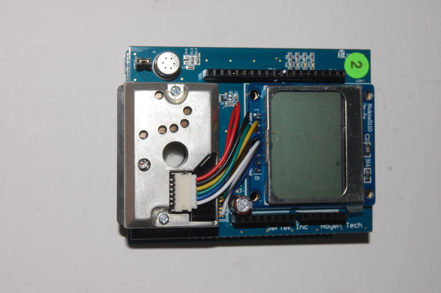
溫溼度整合擴充板(圖片來源/曹建國提供)
Quark SE C1000開發板腳位介紹以及Lumex顯示裝置連接Quark SE C1000開發板兩篇文章中已提過如何設定腳位與裝置連接方式,大家可以點進文章連結參考。
設定並整合好整體電路後,最後再將溫濕度整合擴充板插上,就會看到下圖組合好的完整電路組立。
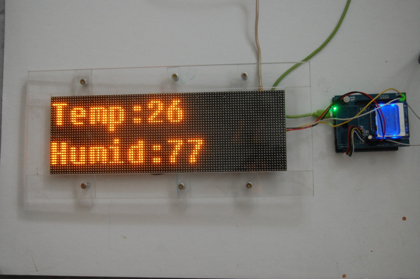
整合溫溼度模組織之電路(圖片來源/曹建國提供)
讀取溫溼度顯示大型螢幕應用
首先,請各位到作者Github,下載Big_LCD.zip。再將載好的檔案匯入到ISSM(Intel System Studio for Microcontroller)後,我們開啟Hello_World_LCD程式。
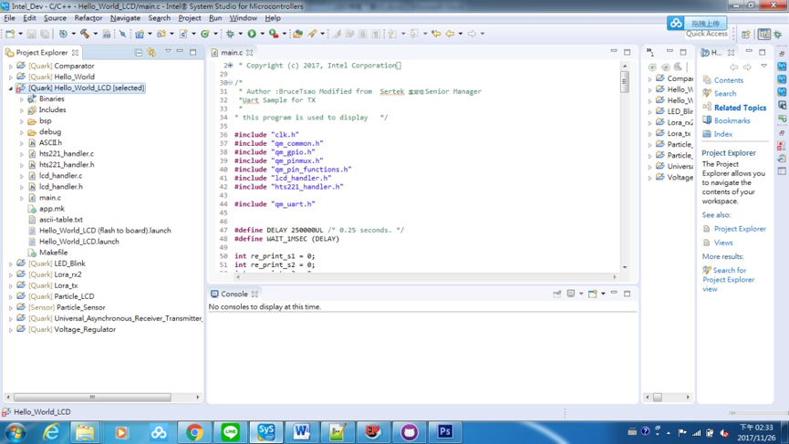
Hello_World_LCD程式(圖片來源/曹建國提供)
我們可以看到許多的程式,在下圖紅框所標示出來的,都是UART範例程式。
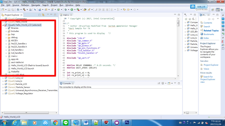
已開啟Hello_World_LCD專案(圖片來源/曹建國提供)
簡化Hello_World_LCD範例講解
下表是Hello_World_LCD範例程式,後續我會一步步解釋:
| /*
* Copyright (c) 2017, Intel Corporation * All rights reserved. * * Redistribution and use in source and binary forms, with or without * modification, are permitted provided that the following conditions are met: * * 1. Redistributions of source code must retain the above copyright notice, * this list of conditions and the following disclaimer. * 2. Redistributions in binary form must reproduce the above copyright notice, * this list of conditions and the following disclaimer in the documentation * and/or other materials provided with the distribution. * 3. Neither the name of the Intel Corporation nor the names of its * contributors may be used to endorse or promote products derived from this * software without specific prior written permission. * * THIS SOFTWARE IS PROVIDED BY THE COPYRIGHT HOLDERS AND CONTRIBUTORS “AS IS” * AND ANY EXPRESS OR IMPLIED WARRANTIES, INCLUDING, BUT NOT LIMITED TO, THE * IMPLIED WARRANTIES OF MERCHANTABILITY AND FITNESS FOR A PARTICULAR PURPOSE * ARE DISCLAIMED. IN NO EVENT SHALL THE INTEL CORPORATION OR CONTRIBUTORS BE * LIABLE FOR ANY DIRECT, INDIRECT, INCIDENTAL, SPECIAL, EXEMPLARY, OR * CONSEQUENTIAL DAMAGES (INCLUDING, BUT NOT LIMITED TO, PROCUREMENT OF * SUBSTITUTE GOODS OR SERVICES; LOSS OF USE, DATA, OR PROFITS; OR BUSINESS * INTERRUPTION) HOWEVER CAUSED AND ON ANY THEORY OF LIABILITY, WHETHER IN * CONTRACT, STRICT LIABILITY, OR TORT (INCLUDING NEGLIGENCE OR OTHERWISE) * ARISING IN ANY WAY OUT OF THE USE OF THIS SOFTWARE, EVEN IF ADVISED OF THE * POSSIBILITY OF SUCH DAMAGE. */
/* * Author :BruceTsao Modified from Sertek 盧育德 Senior Manager *Uart Sample for TX * * this program is used to display */ #include “clk.h” #include “qm_common.h” #include “qm_gpio.h” #include “qm_pinmux.h” #include “qm_pin_functions.h” #include “lcd_handler.h” #include “hts221_handler.h” #include “qm_uart.h”
#define DELAY 250000UL /* 0.25 seconds. */ #define WAIT_1MSEC (DELAY)
int re_print_s1 = 0; int re_print_s2 = 0; int re_print_s3 = 0; int re_print_s4 = 0; int re_print_s5 = 0; uint8_t linefeed[1] = {0x0a} ; int temp = 0; int humid = 0; uint8_t h0t0_l,h0t0_h,h1t0_l,h1t0_h; uint8_t tmp;
static void pin_mux_setup() { // Mux out STDOUT_UART TX/RX pins and enable input for RX. qm_pmux_select(QM_PIN_ID_17, QM_PIN_17_FN_UART1_RXD); qm_pmux_select(QM_PIN_ID_16, QM_PIN_16_FN_UART1_TXD); qm_pmux_input_en(QM_PIN_ID_17, true); } int uint2str(unsigned int no, uint8_t *p) { int ret = 0 ; // int tmp = 0 ; if (no <10) { *p = 0x30 + no ; ret = 1 ; } else if (no <100) {
*(p+1) = 0x30 + (no % 10) ; *p = 0x30 + (int)(no/10) ; ret = 2 ;
}else if (no <1000) { *(p+2) = 0x30 + (no % 10) ; *(p+1) = 0x30 + (int)((no/100) / 10) ; *p = 0x30 + (int)(no/100) ; ret = 3 ;
}else if (no <10000) { *(p+3) = 0x30 + (no % 10) ; *(p+2) = 0x30 + (int)((no % 100) %10) ; *(p+1) = 0x30 + (int)((no % 100) / 10) ; *p = 0x30 + (int)(no/1000) ; ret = 4 ;
} return ret ; }
void SensorData_Print(uint8_t x, uint8_t y, int dec) { uint8_t str5[2] = “%”; if (re_print_s1 || re_print_s2 || re_print_s3 || re_print_s4) LCD_XY_Range_Clear(9, y, 13, y); if (re_print_s1 && (y == 0)) re_print_s1 = 0; else if (re_print_s2 && (y == 1)) re_print_s2 = 0; else if (re_print_s3 && (y == 2)) { LCD_XY_Print_SymIdx(13, 2, 0x64); re_print_s3 = 0; } else if (re_print_s4 && (y == 3)) { LCD_XY_Print(13, 3, str5, 1); re_print_s4 = 0; } else if (re_print_s5 && (y == 4)) re_print_s5 = 0; if (((dec / 100) > 0) && (y == 0)) re_print_s1 = 1; else if (((dec / 100) > 0) && (y == 1)) re_print_s2 = 1; else if (((dec / 100) > 0) && (y == 2)) re_print_s3 = 1; else if (((dec / 100) > 0) && (y == 3)) re_print_s4 = 1; else if (((dec / 100) > 0) && (y == 4)) re_print_s5 = 1; LCD_XY_Print_DecNumb(x, y, dec); }
void lcd_update(int s3, int s4) { #if 0 uint8_t null_str[] = “-“; if (s3) SensorData_Print(9, 2, s3); else LCD_XY_Print(9, 2, null_str, 1);
if (s4) SensorData_Print(9, 3, s4); else LCD_XY_Print(9, 3, null_str, 1);
#endif SensorData_Print(9, 2, s3); SensorData_Print(9, 3, s4); } int main(void) { QM_PUTS(“hello, world”); int strlen = 0;
qm_uart_config_t uart1_cfg ; pin_mux_setup(); uart1_cfg.baud_divisor = QM_UART_CFG_BAUD_DL_PACK(0, 17, 6); uart1_cfg.line_control = QM_UART_LC_8N1; uart1_cfg.hw_fc = false;
qm_uart_set_config(QM_UART_1, &uart1_cfg);
uint8_t str0[] = “MakerPro”; uint8_t str1[13] = “Temperature:”; uint8_t str2[9] = “Humidity:”; uint8_t str3[5] = “Temp:”; uint8_t str4[6] = “Humid:”; uint8_t uart1_message1[20] ;
LCD_Init(); LCD_XY_Print(0, 0, str0, 13); clk_sys_udelay(DELAY*5);
LCD_XY_Print(0, 2, str1, 9); LCD_XY_Print(0, 3, str2, 9); lcd_update(0, 0);
HTS221_Init();
while(1){
temp = HTS221_Tempurature_Read(); humid = HTS221_Humidity_Read();
lcd_update(temp, humid); qm_uart_write_buffer(QM_UART_1, str3, sizeof(str3)); strlen = uint2str(temp, &uart1_message1[0]) ; qm_uart_write_buffer(QM_UART_1, uart1_message1, strlen) ; qm_uart_write_buffer(QM_UART_1, linefeed, 1); qm_uart_write_buffer(QM_UART_1, str4, sizeof(str4)); strlen = uint2str(humid, &uart1_message1[0]) ; qm_uart_write_buffer(QM_UART_1, uart1_message1, strlen) ; clk_sys_udelay(DELAY*10); } return 0; } |
Include講解
下圖所示之程式碼是整個系統必要的含括檔(include files)。
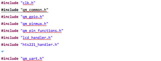
Hello_World_LCD的include程式(圖片來源/曹建國提供)
由於我們需要用到ARD_D0與ARD_D1,這是屬於AP_GPIO_SS9_ADC17_UART1_RXD與AP_GPIO_SS8_ADC16_UART1_TXD,參考下表之SC1000腳位對照表(簡表)所示,UART1_TX與UART1_RX使用到QM_PIN的功能,必須要包含下列三個含括檔:
- #include “qm_pinmux.h”
- #include “qm_common.h”
- #include “qm_pin_functions.h”
由於它仍是GPIO的GPIO_SS[8]與GPIO_SS[9] ,所以必須要包含下列含括檔:
- #include “qm_gpio.h”
- #include “qm_pin_functions.h”
在GPIO的運用中,必須使用上述這些含括檔。
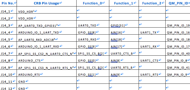
SC1000腳位對照表(簡表)(圖片來源/曹建國提供)
由於UART是使用Universal Asynchronous Receiver Transmitter UART的資源,也關係到UART的QM Function的控制,參考上表所顯示,UART1_TX與UART1_RX使用到Function的控制,必須要包含下列一個含括檔:#include “qm_uart.h”
由於需要延遲顯示會用到系統時間控制,在最後必須要包含下列一個含括檔:#include “clk.h”。
當配合GPIO、通訊埠控制與時間延遲等運用時,都必須要使用到上述的含括檔。
模組Include講解
我們需要用到Nokia 5110 LCD與ST的HTS22溫溼度模組,當我們要開啟lcd_handler.c 、lcd_handler.h、 hts221_handler.c、hts221_handler.h等四支程式時,必須要包含下列兩個含括檔,這是整個系統必要的的含括檔(include files)。
模組的include程式:
| #include “lcd_handler.h”
#include “hts221_handler.h” |
Define宣告講解
系統需要透過define宣告一些特定變數:
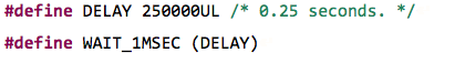
由於需要時間延遲,所以會先定義時間的單位。由於Intel Quark SE C1000開發板的運行是μs := micro second,一秒鐘為一百萬μs,0.25秒為250000UL,所以下列變數定義為:#define DELAY 250000UL。
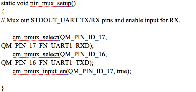
函式內容講解 (pin_mux_setup)
我們需要用到QM Function,而這些QM Function,則需要用到GPIO腳位。使用GPIO時,必須要對腳位使用用途,進行輸入輸出等宣告,所以我們宣告與產生pin_mux_setup()函式來進行上述的用途。
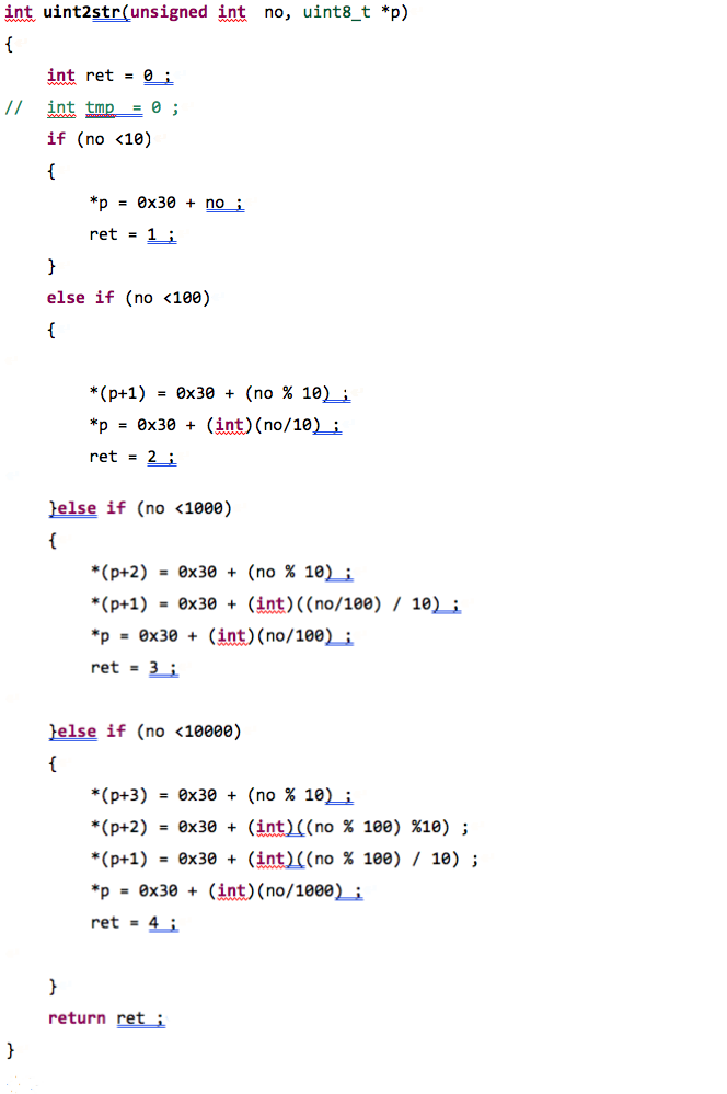
函式內容講解 (uint2str)
由於本專案主要是要把溫濕度感測器的感測數值,顯示在EZDISPLAY大型顯示裝置上,而顯示裝置只接收文字字串,所以宣告一個數字轉字串的自訂函數:uint2str()函數來達到這個功能。
函式內容講解 (SensorData_Print)
透過宣告一個輸出感測資料到LCD顯示裝置自訂函數:SensorData_Print(uint8_t x, uint8_t y, int dec)函數來達到將數值顯示在顯示裝置上的功能。
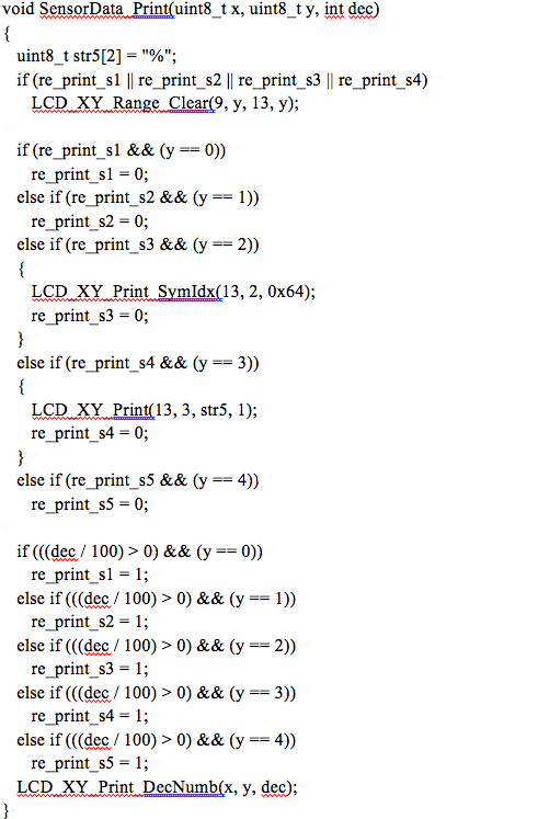
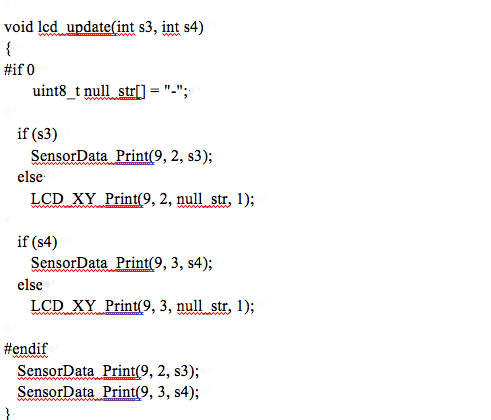
函式內容講解 (lcd_update)
若將宣告LCD顯示裝置更新顯示的自訂函數:SensorData_Print(uint8_t x, uint8_t y, int dec) 函數來達到在EZDISPLAY大型顯示裝置,同時也顯示在Nokia 5110LCD顯示裝置上。
Main主程式講解
下表為main主程式的內容,我們會一一分功能區段,介紹如下:
| int main(void)
{ QM_PUTS(“hello, world”); int strlen = 0; qm_uart_config_t uart1_cfg ; pin_mux_setup(); uart1_cfg.baud_divisor = QM_UART_CFG_BAUD_DL_PACK(0, 17, 6); uart1_cfg.line_control = QM_UART_LC_8N1; uart1_cfg.hw_fc = false; qm_uart_set_config(QM_UART_1, &uart1_cfg); uint8_t str0[] = “MakerPro”; uint8_t str1[13] = “Temperature:”; uint8_t str2[9] = “Humidity:”; uint8_t str3[5] = “Temp:”; uint8_t str4[6] = “Humid:”; uint8_t uart1_message1[20] ; LCD_Init(); LCD_XY_Print(0, 0, str0, 13); clk_sys_udelay(DELAY*5); LCD_XY_Print(0, 2, str1, 9); LCD_XY_Print(0, 3, str2, 9); lcd_update(0, 0); HTS221_Init(); while(1){ temp = HTS221_Tempurature_Read(); humid = HTS221_Humidity_Read(); lcd_update(temp, humid); qm_uart_write_buffer(QM_UART_1, str3, sizeof(str3)); strlen = uint2str(temp, &uart1_message1[0]) ; qm_uart_write_buffer(QM_UART_1, uart1_message1, strlen) ; qm_uart_write_buffer(QM_UART_1, linefeed, 1); qm_uart_write_buffer(QM_UART_1, str4, sizeof(str4)); strlen = uint2str(humid, &uart1_message1[0]) ; qm_uart_write_buffer(QM_UART_1, uart1_message1, strlen) ; clk_sys_udelay(DELAY*10); } return 0; } |
Main主程式:變數宣告
由於我們需要了解溫溼度感測器得到的數值資料,轉成文字字串時其長度為何,所以我們宣告下列變數:int strlen = 0;
在針對QM UART功能進行通訊時所需要的速率、開始位元、結束位元與7 bits / 8 bits等設定,為了這些設定,我們必須宣告下列物件變數:qm_uart_config_t uart1_cfg ;
Main主程式:Setup區
接下來GPIO的設定,之前我們已經介紹pin_mux_setup();函式,因此我們必須在使用GPIO腳位之前,先執行pin_mux_setup();函式內容,所以我們有下列敘述:pin_mux_setup();
Main主程式:通訊設定
設定UART通訊速率中,Lumex Inc. EZDISPLAY顯示裝置的傳輸速率為115200 bps,必須將UART的通訊速率設為115200 bps,以達到同步,所以我們有下列敘述:uart1_cfg.baud_divisor = QM_UART_CFG_BAUD_DL_PACK(0, 17, 6);
接下來,開始UART 通訊方式與格式,主要把通訊格式設為8N1,就是使用8位元傳送,不送Parity bit,停止位元為 bit 1,所以我們有下列敘述:uart1_cfg.line_control = QM_UART_LC_8N1;
最後,在設定UART 是否使用硬體流量控制(flow control及hardware flow control),我們並沒有使用CTS與RTS,所以將硬體的流量控制關閉,我們的下列敘述為:uart1_cfg.hw_fc = false;
上面介紹QM UART功能所訂的物件變數:qm_uart_config_t uart1_cfg ,在上面一連串的設定內容之後,我們需要將這些設定寫入周邊,我們使用qm_uart_set_config()函數寫入,所以我們有下列敘述:qm_uart_set_config(QM_UART_1, &uart1_cfg);
Main主程式:顯示內容變數
接著,要將資訊送往Lumex Inc. EZDISPLAY顯示裝置,但資訊前方仍需資訊顯示欄位說明,因此我們需要資訊顯示欄位說明,變數與資訊內容變數:
uint8_t str0[] = “MakerPro”;
uint8_t str1[13] = “Temperature:”;
uint8_t str2[9] = “Humidity:”;
uint8_t str3[5] = “Temp:”;
uint8_t str4[6] = “Humid:”;
uint8_t uart1_message1[20] ;
其中str0、str1、str2、str3、str4則是顯示內容的前導文字,而uart1_message1[20]為資訊內容變數。
Main主程式:Nokia 5110 LCD顯示區段
透過下表的程式碼,我們可以利用Nokia 5110 LCD顯示區段的程式內容。
| LCD_Init();
LCD_XY_Print(0, 0, str0, 13); clk_sys_udelay(DELAY*5);
LCD_XY_Print(0, 2, str1, 9); LCD_XY_Print(0, 3, str2, 9); lcd_update(0, 0); |
LCD_Init()主要是Nokia 5110 LCD顯示裝置初始化的程式,而LCD_XY_Print()則是將預先顯示前到文字顯示,最後用lcd_update(0, 0); 將內容直接顯示Nokia 5110 LCD顯示裝置。
Main主程式:HTS221_Init 區段
在開始讀取STMicroelectronics出產的HTS221:Capacitive digital sensor for relative humidity and temperature 溫溼度感測裝置,我們必須先初始化感測裝置,使用HTS221_Init(); 開啟溫溼度感測裝置。
Main主程式:loop()區段
一般熟悉Arduino 開發版開發系統的讀者,都會了解Arduino 開發版固定有一個loop()迴圈的程式區段,這段是固定的區域,而且在Arduino 開發時,固定有一塊loop()迴圈的程式區段。這段程式區段是必須且一定存在的,然而在Intel Quark SE C1000開發板,是遵循一般C語言開發方式,所以並沒有像Arduino 開發時,固定有一塊loop()迴圈的程式區段,所以我們用永久迴圈來達到這個效果。
如下表所示,我們可以看到我們用while(1){……}的方式來達到類似loop()迴圈的程式區段。
| while(1){
clk_sys_udelay(DELAY*10); temp = HTS221_Tempurature_Read(); humid = HTS221_Humidity_Read(); lcd_update(temp, humid); qm_uart_write_buffer(QM_UART_1, str3, sizeof(str3)); strlen = uint2str(temp, &uart1_message1[0]) ; qm_uart_write_buffer(QM_UART_1, uart1_message1, strlen) ; qm_uart_write_buffer(QM_UART_1, linefeed, 1); qm_uart_write_buffer(QM_UART_1, str4, sizeof(str4)); strlen = uint2str(humid, &uart1_message1[0]) ; qm_uart_write_buffer(QM_UART_1, uart1_message1, strlen) ; } return 0; } |
我們因為顯示內容不一定跟上感測器偵測速率等因素,所以必須用延遲等待的函數如delay()(Arduino 指令),使用之前系統的函數clk_sys_udelay()來達到時間延遲的效果,將敘述設為:clk_sys_udelay(DELAY*10);
其WAIT_1MSEC為一百萬的us,所以我們延遲一秒鐘。
Main主程式:讀取溫溼度感測器
下表所示,我們用HTS221_Tempurature_Read()來讀取溫溼度感測器的溫度並存回temp變數;用HTS221_Humidity_Read();來讀取溫溼度感測器之濕度並存回humid變數:
| temp = HTS221_Tempurature_Read();
humid = HTS221_Humidity_Read(); lcd_update(temp, humid); |
接下來我們將溫溼度變數:temp變數與humid變數,透過lcd_update(temp, humid);將溫溼度數值,送到nokia 5110 lcd顯示裝置。
Main主程式:送出溫度資料到大型顯示器
利用該表程式碼,將溫度資料傳送到大型顯示器上:
| qm_uart_write_buffer(QM_UART_1, str3, sizeof(str3));
strlen = uint2str(temp, &uart1_message1[0]) ; qm_uart_write_buffer(QM_UART_1, uart1_message1, strlen) ; |
我們用qm_uart_write_buffer(QM_UART_1, str3, sizeof(str3)); 將”Temp:”送到大型顯示裝置。
strlen = uint2str(temp, &uart1_message1[0]) ;
接著,用uint2str(temp, &uart1_message1[0])將溫度變數: temp變數轉到uart1_message1陣列中,並將temp變數轉成文字的總長度回傳到strlen變數:qm_uart_write_buffer(QM_UART_1, uart1_message1, strlen) ;
最後,用qm_uart_write_buffer(QM_UART_1, uart1_message1, strlen)將uart1_message1陣列內容就可以將資料送到大型顯示裝置。
Main主程式:傳送換行鍵到大型顯示器
用qm_uart_write_buffer(QM_UART_1, linefeed, 1);將linefeed變數(換行符號),送到大型顯示裝置,讓後續在傳送的資訊之前,先進行換行的動作。 qm_uart_write_buffer(QM_UART_1, linefeed, 1);
Main主程式:送出濕度資料到大型顯示器
利用該表程式碼,將濕度資料傳送到大型顯示器上:
| qm_uart_write_buffer(QM_UART_1, str4, sizeof(str4));
strlen = uint2str(humid, &uart1_message1[0]) ; qm_uart_write_buffer(QM_UART_1, uart1_message1, strlen) ; |
用qm_uart_write_buffer(QM_UART_1, str4, sizeof(str4));將”Humid:”送到大型顯示裝置。
strlen = uint2str(humid, &uart1_message1[0]) ;
接著,用uint2str(humid, &uart1_message1[0])將濕度變數:humid變數轉到uart1_message1陣列中,並將humid變數轉成文字的總長度回傳到strlen變數:qm_uart_write_buffer(QM_UART_1, uart1_message1, strlen) ;
再來,用qm_uart_write_buffer(QM_UART_1, uart1_message1, strlen)將uart1_message1陣列內容送到大型顯示裝置。
燒錄測試
點選下圖紅框處,選Hello_World_LCD (Flash to Board),進行燒錄程式到Intel Quark SE C1000開發板的燒錄功能是否正確。
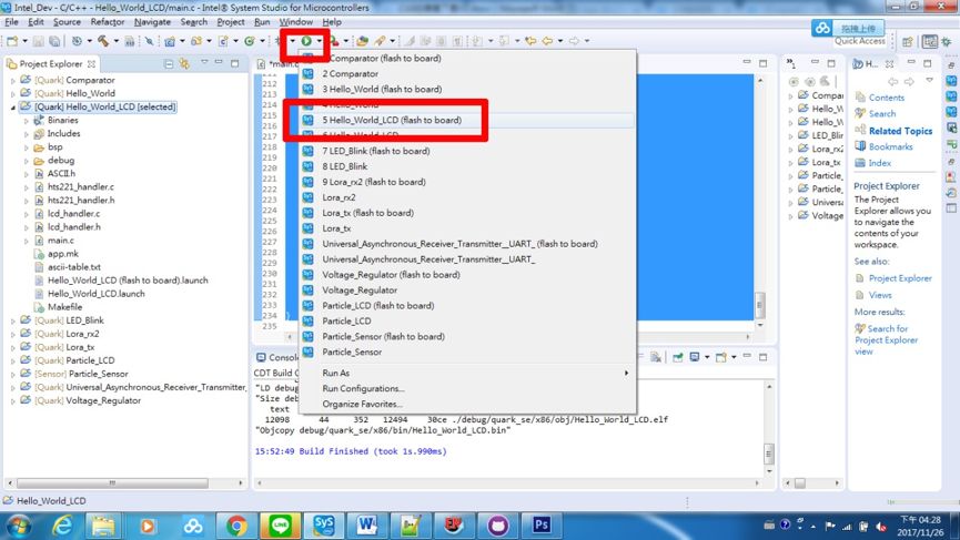
燒錄Hello_World_LCD程式到開發板(圖片來源/曹建國提供)
如下圖所示,如果沒有任何錯誤的訊息出現,則代表我們完成燒錄程式到開發板的作業。
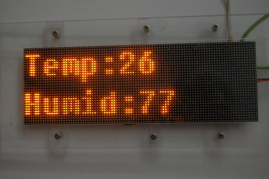
執行Hello_World_LCD內容(圖片來源/曹建國提供)
(責任編輯:葉于甄)
◎加入我們的Line,獲得更多及時文章更新&活動資訊→

- 【大氣監控站台開發案例(下)】環境監控即時監控看板 - 2021/11/25
- 【大氣監控站台開發案例(中)】環境監控雲端平台系統介紹 - 2021/11/02
- 【大氣監控站台開發案例(上)】 大氣監控站建置實例介紹 - 2021/10/18
訂閱MakerPRO知識充電報
與40000位開發者一同掌握科技創新的技術資訊!


