作者:Ches拔
不知道各位有沒有觀察過 Tracker 這類型的產品?例如台廠出貨量大的 GPS人員追蹤器、LoRa + GPS的多用途功能型追蹤器、以及募資成功的 lota 狗狗貓貓寵物追蹤器 - 這個也可以拿來做導遊帶團的人員追蹤。
為什麼要製作追蹤器?
這次要做的是LoRa + GPS + SOS 按鍵追蹤器,起因是有社群的朋友問到,既然indoor location 我們都做了,那 outdoor 呢?其實原本不太想寫這篇的,因為市面上太多同類型產品可挑選,但為了讓社群朋友知道這個專案能做的真的非常、非常多,連室外定位也可以設定為長照的一個分支。
這一篇是由MakerPRO社群賴桑的兩篇文章修改而來:
1、用 LinkIt 7697 完成能偵測跌倒的手環
2、用 LinkIt 7697 製作跌倒偵測裝置
所需材料介紹
我們的做法非常簡單:LinkIt 7697 + MPU6050 + Button + GPS module + LoRa,這樣就搞定啦!
光華商場一顆 MPU6050 + Button 不用130元,GPS module 我是買 Ublox 的,但其實哪一家都可以,價格1000元以內就行,因為這種 GPS module 只會有4支腳(VCC GND TX RX),接到LinkIt 7697就可以了。
LoRa 則是之前參加 MakerPRO 主辦的自造松所留下的材料,也可以在沒屋頂的拍賣場搜尋柯大創客屋購買。所以,製作手環要花大約2000元,如果再加上前一篇做的智障型燈座,這樣要2塊LinkIt 7697,總價大約為2500元。
咦!比 lota 的 early bird USD99 還便宜耶!這樣知道為什麼歐美市場比較好賺了吧,2500NTD放在台灣誰要買?台灣人力最便宜了,寵物跑了就叫消防隊找囉。
但其實這種想法跟最近幾年大家開始重視汽車的安全性,主、被動安全都要顧及,而不是省油省到爆,讓整個城市都是我的潰縮區是一樣的。市場需要被教育,但教育會花、很、長、的時間。
開始製作追蹤器吧!
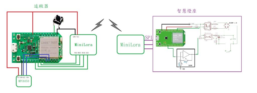
這次的電路架構如下圖,左邊是要做出來的 SOS 跌倒追蹤器,右邊是上一篇的近端遙控智障型燈座:
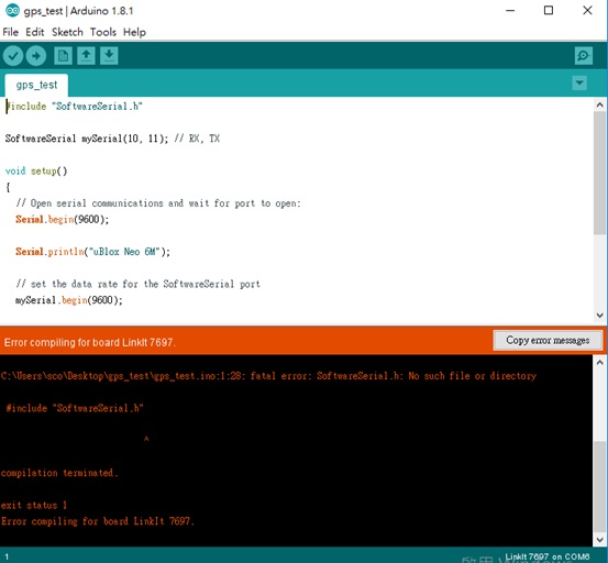
經過上一篇的洗禮,決定先用手邊的 Arduino Yun 做,不然又被 Linkit 7697 坑到⋯⋯Arduino Yun 的做法相當簡單,我已經很習慣在開始之前先上 Github 看看有沒有勇士分享文章,結果真的被我找到啦!出來吧!勇士!
這是一句那美克星語「出來吧!神龍!」
文章是在說明如何使用 Aduino Yun 的 SoftwareSerial 取出 GPS 數據,簡易的code如下:
#include “SoftwareSerial.h”
SoftwareSerial mySerial(10, 11); // RX, TX
void setup()
{
// Open serial communications and wait for port to open:
Serial.begin(9600);
Serial.println(“uBlox Neo 6M”);
// set the data rate for the SoftwareSerial port
mySerial.begin(9600);
}
void loop()
{
if (mySerial.available())
Serial.write(mySerial.read());
}
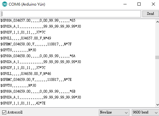
輸出如下圖:
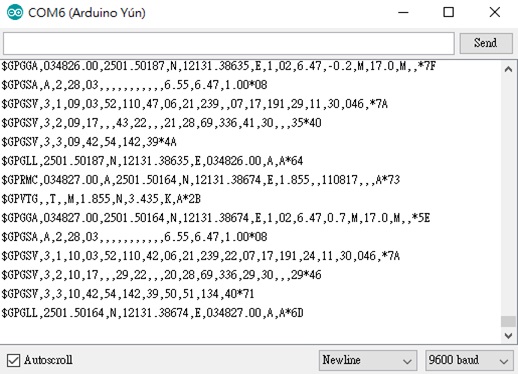
GPS科普時間
GPS 有許多有用的資料格式,GPGGA UTC時間、緯度值、經度值、對地速度、日期、定位狀態、觀測的GPS衛星個數、差分基準站編號⋯⋯在這裡,我們只要 GPRMC 或是 GPGGA 內的 2501.50164 與 12131.38674 就行了,但這代表什麼意思呢?用網頁來輸入經緯度 2501.50164, 12131.38674 看看:
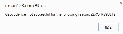
輸入後,出現上圖,代表圖資是不吃這種格式的,所以需要轉換格式:
1、首先直接除以100,2501.50164/100=25.0150164
2、把小數點的0.0150164轉為150164
3、然後(150164/60)*10000=250273333.3
4、第二步移了一個0,所以轉小數的時候,多加一個0.02502733333
5、緯度=25+0.02502733333=25. 02502733333
1、首先直接除以100,12131.38674/100=121.313867
2、把小數點轉為313867
3、然後(313867/60)*10000=52311166.7
4、經度=121+0.52311166=121.523111667
所以轉換後的數值是 25.02502733333, 121.523111667~來試試有沒有這個地方:
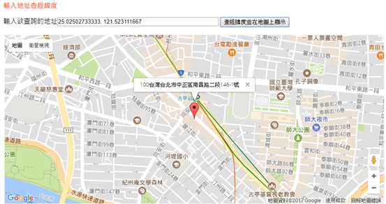
地圖顯示我在台北市中正區南昌路二段146-1號,其實我是在 MakerPRO辦公室的樓下。為什麼要在樓下而不在辦公室內呢?因為衛星是在地球上方,而 GPS 模組是在地面上收訊息,所以在家裡吹冷氣寫 code,會發現 GPS 收不到訊號,圖示如下:
在上一步會知道,只取出GPS格式是沒用的,圖資不吃這套格式,還是得轉換一下,所以就用了這篇。在 Arduino Yun 上 GPS 的 code 會是這樣(主要是紅字的部份,不要被大量的 code 嚇到):
boolean gpsStatus[] = {false, false, false, false, false, false, false};
unsigned long start;
boolean grabNext = false;
int pointerGPS = 0;
String dataGPS[6] ;
uint8_t hour,minute,second;
float buf1, buf2, buf3;
#include <SoftwareSerial.h>
SoftwareSerial gpsSerial(10, 11); // RX, TX
void setup()
{
gpsSerial.begin(9600);
// START OUR SERIAL DEBUG PORT
Serial.begin(115200);
//
//Settings Array contains the following settings: [0]NavMode, [1]DataRate1, [2]DataRate2, [3]PortRateByte1, [4]PortRateByte2, [5]PortRateByte3,
//[6]NMEA GLL Sentence, [7]NMEA GSA Sentence, [8]NMEA GSV Sentence, [9]NMEA RMC Sentence, [10]NMEA VTG Sentence
//NavMode:
//Pedestrian Mode = 0x03
//Automotive Mode = 0x04
//Sea Mode = 0x05
//Airborne < 1G Mode = 0x06
//
//DataRate:
//1Hz = 0xE8 0x03
//2Hz = 0xF4 0x01
//3.33Hz = 0x2C 0x01
//4Hz = 0xFA 0x00
//
//PortRate:
//4800 = C0 12 00
//9600 = 80 25 00
//19200 = 00 4B 00 **SOFTWARESERIAL LIMIT FOR ARDUINO UNO R3!**
//38400 = 00 96 00 **SOFTWARESERIAL LIMIT FOR ARDUINO MEGA 2560!**
//57600 = 00 E1 00
//115200 = 00 C2 01
//230400 = 00 84 03
//
//NMEA Messages:
//OFF = 0x00
//ON = 0x01
//
byte settingsArray[] = {0x03, 0xFA, 0x00, 0x00, 0xE1, 0x00, 0x00, 0x00, 0x00, 0x00, 0x00}; //
configureUblox(settingsArray);
}
double convertDegMinToDecDeg (float degMin) {
double min = 0.0;
double decDeg = 0.0;
//get the minutes, fmod() requires double
min = fmod((double)degMin, 100.0);
//rebuild coordinates in decimal degrees
degMin = (int) ( degMin / 100 );
decDeg = degMin + ( min / 60 );
return decDeg;
}
void loop()
{
char recvChar;
String sentence;
while(1) {
if(gpsSerial.available())
{
// THIS IS THE MAIN LOOP JUST READS IN FROM THE GPS SERIAL AND ECHOS OUT TO THE ARDUINO SERIAL.
recvChar = gpsSerial.read();
if(String(recvChar) == “,”) {
if(grabNext){
dataGPS[pointerGPS] = sentence;
//Serial.println(dataGPS[pointerGPS]);
pointerGPS = pointerGPS -1;
if(pointerGPS <1){
grabNext = false;
// print out data
/* Serial.println(dataGPS[5]); // Time
Serial.print(dataGPS[4]);
Serial.println(dataGPS[3]); // North
Serial.print(dataGPS[2]);
Serial.println(dataGPS[1]); // West*/
dataGPS[5].toInt();
hour = dataGPS[5].toInt()/10000+8;
minute = (dataGPS[5].toInt()/100) %100;
second = dataGPS[5].toInt() %100;
Serial.print(“Time:”); // Time
Serial.print(hour);
Serial.print(“:”);
Serial.print(minute);
Serial.print(“:”);
Serial.println(second);
buf1 = dataGPS[4].toFloat();
buf2 = dataGPS[2].toFloat();
Serial.print(“Lat, Lon:”); //Lat, Lon
Serial.print(convertDegMinToDecDeg(buf1),6);
Serial.print(“,”);
Serial.println(convertDegMinToDecDeg(buf2),6);
}
}
if(sentence == “M$GPGGA”){
grabNext = true;
pointerGPS = 5;
}
sentence =””;
}
else{
sentence = sentence + String(recvChar);
}
}
}
}
void configureUblox(byte *settingsArrayPointer) {
byte gpsSetSuccess = 0;
Serial.println(“Configuring u-Blox GPS initial state…”);
//Generate the configuration string for Navigation Mode
byte setNav[] = {0xB5, 0x62, 0x06, 0x24, 0x24, 0x00, 0xFF, 0xFF, *settingsArrayPointer, 0x03, 0x00, 0x00, 0x00, 0x00, 0x10, 0x27, 0x00, 0x00, 0x05, 0x00, 0xFA, 0x00, 0xFA, 0x00, 0x64, 0x00, 0x2C, 0x01, 0x00, 0x00, 0x00, 0x00, 0x00, 0x00, 0x00, 0x00, 0x00, 0x00, 0x00, 0x00, 0x00, 0x00, 0x00, 0x00};
calcChecksum(&setNav[2], sizeof(setNav) – 4);
//Generate the configuration string for Data Rate
byte setDataRate[] = {0xB5, 0x62, 0x06, 0x08, 0x06, 0x00, settingsArrayPointer[1], settingsArrayPointer[2], 0x01, 0x00, 0x01, 0x00, 0x00, 0x00};
calcChecksum(&setDataRate[2], sizeof(setDataRate) – 4);
//Generate the configuration string for Baud Rate
byte setPortRate[] = {0xB5, 0x62, 0x06, 0x00, 0x14, 0x00, 0x01, 0x00, 0x00, 0x00, 0xD0, 0x08, 0x00, 0x00, settingsArrayPointer[3], settingsArrayPointer[4], settingsArrayPointer[5], 0x00, 0x07, 0x00, 0x03, 0x00, 0x00, 0x00, 0x00, 0x00, 0x00, 0x00};
calcChecksum(&setPortRate[2], sizeof(setPortRate) – 4);
byte setGLL[] = {0xB5, 0x62, 0x06, 0x01, 0x08, 0x00, 0xF0, 0x01, 0x00, 0x00, 0x00, 0x00, 0x00, 0x01, 0x01, 0x2B};
byte setGSA[] = {0xB5, 0x62, 0x06, 0x01, 0x08, 0x00, 0xF0, 0x02, 0x00, 0x00, 0x00, 0x00, 0x00, 0x01, 0x02, 0x32};
byte setGSV[] = {0xB5, 0x62, 0x06, 0x01, 0x08, 0x00, 0xF0, 0x03, 0x00, 0x00, 0x00, 0x00, 0x00, 0x01, 0x03, 0x39};
byte setRMC[] = {0xB5, 0x62, 0x06, 0x01, 0x08, 0x00, 0xF0, 0x04, 0x00, 0x00, 0x00, 0x00, 0x00, 0x01, 0x04, 0x40};
byte setVTG[] = {0xB5, 0x62, 0x06, 0x01, 0x08, 0x00, 0xF0, 0x05, 0x00, 0x00, 0x00, 0x00, 0x00, 0x00, 0x04, 0x46};
delay(2500);
while(gpsSetSuccess < 3)
{
Serial.print(“Setting Navigation Mode… “);
sendUBX(&setNav[0], sizeof(setNav)); //Send UBX Packet
gpsSetSuccess += getUBX_ACK(&setNav[2]); //Passes Class ID and Message ID to the ACK Receive function
if (gpsSetSuccess == 5) {
gpsSetSuccess -= 4;
setBaud(settingsArrayPointer[4]);
delay(1500);
byte lowerPortRate[] = {0xB5, 0x62, 0x06, 0x00, 0x14, 0x00, 0x01, 0x00, 0x00, 0x00, 0xD0, 0x08, 0x00, 0x00, 0x80, 0x25, 0x00, 0x00, 0x07, 0x00, 0x03, 0x00, 0x00, 0x00, 0x00, 0x00, 0xA2, 0xB5};
sendUBX(lowerPortRate, sizeof(lowerPortRate));
gpsSerial.begin(9600);
delay(2000);
}
if(gpsSetSuccess == 6) gpsSetSuccess -= 4;
if (gpsSetSuccess == 10) gpsStatus[0] = true;
}
if (gpsSetSuccess == 3) Serial.println(“Navigation mode configuration failed.”);
gpsSetSuccess = 0;
while(gpsSetSuccess < 3) {
Serial.print(“Setting Data Update Rate… “);
sendUBX(&setDataRate[0], sizeof(setDataRate)); //Send UBX Packet
gpsSetSuccess += getUBX_ACK(&setDataRate[2]); //Passes Class ID and Message ID to the ACK Receive function
if (gpsSetSuccess == 10) gpsStatus[1] = true;
if (gpsSetSuccess == 5 | gpsSetSuccess == 6) gpsSetSuccess -= 4;
}
if (gpsSetSuccess == 3) Serial.println(“Data update mode configuration failed.”);
gpsSetSuccess = 0;
while(gpsSetSuccess < 3 && settingsArrayPointer[6] == 0x00) {
Serial.print(“Deactivating NMEA GLL Messages “);
sendUBX(setGLL, sizeof(setGLL));
gpsSetSuccess += getUBX_ACK(&setGLL[2]);
if (gpsSetSuccess == 10) gpsStatus[2] = true;
if (gpsSetSuccess == 5 | gpsSetSuccess == 6) gpsSetSuccess -= 4;
}
if (gpsSetSuccess == 3) Serial.println(“NMEA GLL Message Deactivation Failed!”);
gpsSetSuccess = 0;
while(gpsSetSuccess < 3 && settingsArrayPointer[7] == 0x00) {
Serial.print(“Deactivating NMEA GSA Messages “);
sendUBX(setGSA, sizeof(setGSA));
gpsSetSuccess += getUBX_ACK(&setGSA[2]);
if (gpsSetSuccess == 10) gpsStatus[3] = true;
if (gpsSetSuccess == 5 | gpsSetSuccess == 6) gpsSetSuccess -= 4;
}
if (gpsSetSuccess == 3) Serial.println(“NMEA GSA Message Deactivation Failed!”);
gpsSetSuccess = 0;
while(gpsSetSuccess < 3 && settingsArrayPointer[8] == 0x00) {
Serial.print(“Deactivating NMEA GSV Messages “);
sendUBX(setGSV, sizeof(setGSV));
gpsSetSuccess += getUBX_ACK(&setGSV[2]);
if (gpsSetSuccess == 10) gpsStatus[4] = true;
if (gpsSetSuccess == 5 | gpsSetSuccess == 6) gpsSetSuccess -= 4;
}
if (gpsSetSuccess == 3) Serial.println(“NMEA GSV Message Deactivation Failed!”);
gpsSetSuccess = 0;
while(gpsSetSuccess < 3 && settingsArrayPointer[9] == 0x00) {
Serial.print(“Deactivating NMEA RMC Messages “);
sendUBX(setRMC, sizeof(setRMC));
gpsSetSuccess += getUBX_ACK(&setRMC[2]);
if (gpsSetSuccess == 10) gpsStatus[5] = true;
if (gpsSetSuccess == 5 | gpsSetSuccess == 6) gpsSetSuccess -= 4;
}
if (gpsSetSuccess == 3) Serial.println(“NMEA RMC Message Deactivation Failed!”);
gpsSetSuccess = 0;
while(gpsSetSuccess < 3 && settingsArrayPointer[10] == 0x00) {
Serial.print(“Deactivating NMEA VTG Messages “);
sendUBX(setVTG, sizeof(setVTG));
gpsSetSuccess += getUBX_ACK(&setVTG[2]);
if (gpsSetSuccess == 10) gpsStatus[6] = true;
if (gpsSetSuccess == 5 | gpsSetSuccess == 6) gpsSetSuccess -= 4;
}
if (gpsSetSuccess == 3) Serial.println(“NMEA VTG Message Deactivation Failed!”);
gpsSetSuccess = 0;
if (settingsArrayPointer[4] != 0x25) {
Serial.print(“Setting Port Baud Rate… “);
sendUBX(&setPortRate[0], sizeof(setPortRate));
setBaud(settingsArrayPointer[4]);
Serial.println(“Success!”);
delay(500);
}
}
void calcChecksum(byte *checksumPayload, byte payloadSize) {
byte CK_A = 0, CK_B = 0;
for (int i = 0; i < payloadSize ;i++) {
CK_A = CK_A + *checksumPayload;
CK_B = CK_B + CK_A;
checksumPayload++;
}
*checksumPayload = CK_A;
checksumPayload++;
*checksumPayload = CK_B;
}
void sendUBX(byte *UBXmsg, byte msgLength) {
for(int i = 0; i < msgLength; i++) {
gpsSerial.write(UBXmsg[i]);
gpsSerial.flush();
}
gpsSerial.println();
gpsSerial.flush();
}
byte getUBX_ACK(byte *msgID) {
byte CK_A = 0, CK_B = 0;
byte incoming_char;
boolean headerReceived = false;
unsigned long ackWait = millis();
byte ackPacket[10] = {0xB5, 0x62, 0x05, 0x00, 0x00, 0x00, 0x00, 0x00, 0x00, 0x00};
int i = 0;
while (1) {
if (gpsSerial.available()) {
incoming_char = gpsSerial.read();
if (incoming_char == ackPacket[i]) {
i++;
}
else if (i > 2) {
ackPacket[i] = incoming_char;
i++;
}
}
if (i > 9) break;
if ((millis() – ackWait) > 1500) {
Serial.println(“ACK Timeout”);
return 5;
}
if (i == 4 && ackPacket[3] == 0x00) {
Serial.println(“NAK Received”);
return 1;
}
}
for (i = 2; i < 8 ;i++) {
CK_A = CK_A + ackPacket[i];
CK_B = CK_B + CK_A;
}
if (msgID[0] == ackPacket[6] && msgID[1] == ackPacket[7] && CK_A == ackPacket[8] && CK_B == ackPacket[9]) {
Serial.println(“Success!”);
Serial.print(“ACK Received! “);
printHex(ackPacket, sizeof(ackPacket));
return 10;
}
else {
Serial.print(“ACK Checksum Failure: “);
printHex(ackPacket, sizeof(ackPacket));
delay(1000);
return 1;
}
}
void printHex(uint8_t *data, uint8_t length) // prints 8-bit data in hex
{
char tmp[length*2+1];
byte first ;
int j=0;
for (byte i = 0; i < length; i++)
{
first = (data[i] >> 4) | 48;
if (first > 57) tmp[j] = first + (byte)7;
else tmp[j] = first ;
j++;
first = (data[i] & 0x0F) | 48;
if (first > 57) tmp[j] = first + (byte)7;
else tmp[j] = first;
j++;
}
tmp[length*2] = 0;
for (byte i = 0, j = 0; i < sizeof(tmp); i++) {
Serial.print(tmp[i]);
if (j == 1) {
Serial.print(” “);
j = 0;
}
else j++;
}
Serial.println();
}
void setBaud(byte baudSetting) {
if (baudSetting == 0x12) gpsSerial.begin(4800);
if (baudSetting == 0x4B) gpsSerial.begin(19200);
if (baudSetting == 0x96) gpsSerial.begin(38400);
if (baudSetting == 0xE1) gpsSerial.begin(57600);
if (baudSetting == 0xC2) gpsSerial.begin(115200);
if (baudSetting == 0x84) gpsSerial.begin(230400);
}
這裡印出的東西非常簡單,就是 GPS 轉換過後的數據,由於沒存到圖,又剛好在室內寫文章,故示意圖如下:
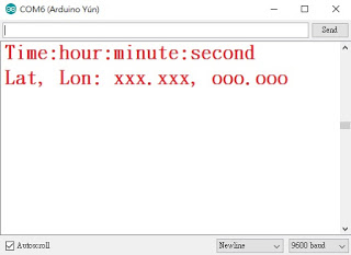
好了,Arduino Yun 可以了,換上 LinkIt 7697 吧!先用簡單的 code:
void setup(){
Serial.begin(9600);
Serial.println(“Hello”);
}
void loop(){
Serial.println( Serial.read());
}
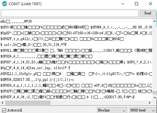
結果會如下圖:
我的天~天~天~啊!連食尚玩家的阿松都發現了我們找到了第4個 bug!
為什麼看別人的文章都沒在寫bug,我好像在做 LinkIt 7697 QA bug report。這個 bug 是代表 LinkIt 7697 不能使用 SoftwareSerial.h,也就是說沒辦法自定腳位給 GPS 模組使用,只能用實體 UART 給 GPS 用。好吧~那我們就來接 LinkIt 7697 的實體 UART pin0 與 pin1 吧!但因為 pin0 與 pin1 已經給 USB Debug 用了,所以再接上 GPS 模組會出現亂碼:
天怒人怨啊!森77!!

這表示 LinkIt 7697 開發不能外接 GPS/3G/4G⋯⋯等 UART 模組?其實 Arduino Yun 開發完了就可以直接換上 LinkIt 7697,因為 USB Debug 不會再用到了。所以這次就用 Arduino Yun 開發手環連接到燈座,有朋友問到,那不如改用 ESP32?也是 BLE+WiFi,用ESP32當然也行,因為我們的功能不會非常複雜。

但⋯⋯我們要支持可以跟國際市場抗衡的國貨,而不是盲目地支持國貨,相信這4個 bug只是 MTK QA 沒查到,也許下一版更新就改過來了。

復習一下另外3個 bug:
1、Linkit7697 Arduino IDE的WiFi設定,無法AP/Station轉換
2、Linkit7697 Arduino IDE內的BLE Characteristic最多只能4個,再多就當機
3、Linkit7697 Arduino IDE內的attachInterrupt(),掃瞄速度不夠快,會直接罷工
MTK還有論壇哦!有問題可以 po 上去詢問,但可能 MTKer 比較忙,又常加班的關係,如果曾用過 TI、Espressif、Realtek 論壇,就會發現MTK回應速度⋯⋯對比先前用過對岸的 Realtek QQ 群組,只能用火速來形容,這也是為什麼 Espressif 會在全球 Maker 圈中火熱起來,除了很清楚 Maker 要什麼之外,回應速度也飛快啊!
好了,抱怨結束,讓我們回到正題!接下來把賴桑的 code 擷取下來:
#include “I2Cdev.h”#include “MPU6050.h”#include “Wire.h”MPU6050 accelgyro;int16_t ax, ay, az;int16_t gx, gy, gz;int time_interval = 500; //500msunsigned long current, lastTime = 0;int16_t prev_accx = 0;int16_t prev_accy = 0;int16_t prev_accz = 0;float acc_upv = 2.8; //The thresholds for fall detectionvoid setup(){Wire.begin();Serial.begin(115200);accelgyro.initialize();accelgyro.getMotion6(&ax, &ay, &az, &gx, &gy, &gz);prev_accx = ax;prev_accy = ay;prev_accz = az;lastTime = millis();}void loop(){current = millis(); //Set for every intervalif(current – lastTime >= time_interval){lastTime = current;accelgyro.getMotion6(&ax, &ay, &az, &gx, &gy, &gz);float accx = ((ax – prev_accx) / 16384) * ((ax – prev_accx) / 16384);float accy = ((ay – prev_accy) / 16384) * ((ay – prev_accy) / 16384);float accz = ((az – prev_accz) / 16384) * ((az – prev_accz) / 16384);Serial.print(accx); Serial.print(“\t”);Serial.print(accy); Serial.print(“\t”);Serial.print(accz); Serial.println();if( sqrt(accx + accy + accz) > acc_upv )Serial.println(“GOT!!!”);prev_accx = ax;prev_accy = ay;prev_accz = az;}}
然後再把柯大的 MiniLora Example,LoraSender 與 LoRaReceiver 貼出來:
LoraSender →
#include <SPI.h>
#include <LoRa.h>
int counter = 0;
void setup() {
Serial.begin(9600);
while (!Serial);
Serial.println(“LoRa Sender”);
if (!LoRa.begin(915E6)) {
Serial.println(“Starting LoRa failed!”);
while (1);
}
}
void loop() {
Serial.print(“Sending packet: “);
Serial.println(counter);
// send packet
LoRa.beginPacket();
LoRa.print(“hello “);
LoRa.print(counter);
LoRa.endPacket();
counter++;
delay(5000);
}
LoRaReceiver →
#include “SPI.h”
#include <LoRa.h>
void setup() {
Serial.begin(9600);
while (!Serial);
Serial.println(“LoRa Receiver”);
if (!LoRa.begin(915E6)) {
Serial.println(“Starting LoRa failed!”);
while (1);
}
}
void loop() {
// try to parse packet
int packetSize = LoRa.parsePacket();
if (packetSize) {
// received a packet
Serial.print(“Received packet ‘”);
// read packet
while (LoRa.available()) {
Serial.print((char)LoRa.read());
}
// print RSSI of packet
Serial.print(“‘ with RSSI “);
Serial.println(LoRa.packetRssi());
}
}
Sender 是用在 Arduino Yun 上面,MPU6050 判斷長輩跌倒或由按下 Button 送出 Trigger 訊號及 GPS 位置到燈座,而 Receiver 是用在 Linkit7697 上的 code,其實 Receiver 將來需要修正,因為手機需要下指令到燈座,再由燈座送訊號到手環取得 GPS 位置。流程如下:
手機 → Cloud Server → 燈座 → 手環
手環回傳GPS位置 → 燈座 → Cloud Server → 手機
我猜測 lota 的架構大概也是這個樣子,這次留下4個 Part 的 Code 給大家手動實驗。我先去 104 投 MTK 的 QA 了,希望也可以負責論壇這一塊 ~
面試小劇場
主審官:

我:ㄜ⋯⋯
主審官:

我:鳴⋯⋯
結語
之後的實做文章應該只剩下2至3篇,主要是燈座連接到智能家居配件(smart home security)及燈座室內定位,就結束了~接下來會找時間開個線上會議,看看大家對Simple Care這個群組有什麼想法,基本上,Simple care is yours——怎麼讓照護變得更簡單?如何內化目前專案?怎麼整合照護人員及最後一哩路?這些都是我們要好好討論和思考的!
這個專案整合了四大領域:長照、保全、室內定位及智能燈泡,再細分下去還有 Big data、AI、IoT⋯⋯要做的事太多了!而這個群組內的參與人員領域很廣,也希望大家能多多為這個社會盡一份力。
Good Luck! 最後⋯⋯加入我們吧!一起動手改變世界 !
(本文同步發表於作者部落格「物聯網學習筆記1」,文章連結;責任編輯:林佳盈)
◎加入我們的Line,獲得更多及時文章更新&活動資訊→
![]()

- 【育教於樂】我家日常的康達效應 - 2019/04/25
- 【Tutorial】一起走進 ROS 的世界吧(5) - 語音辨識篇 - 2018/12/26
- 【Tutorial】一起走進 ROS 的世界吧(4) — 視覺辨識篇 - 2018/11/14
訂閱MakerPRO知識充電報
與40000位開發者一同掌握科技創新的技術資訊!


